
Main Parachute Release Device
| Rocketry Home |
| Feretich Home |
For our Super-ARLISS project, we needed a way to deploy both drogue and main parachutes from the same compartment. We also wanted to perform the deployment with a minimum of black powder. We selected Rouse-Tech CD3 deployment for the drogue parachute. The CD3's require only about 0.1 grams of black powder to open a CO2 gas cartridge. The CO2 gas separates the rocket sections and deploy the drogue parachute. Now we needed a way to retain the main parachute inside the compartment until the flight computer determined that it was to be deployed.
Project Goals
- Reliably eject and deploy a main parachute from an open compartment at a time chosen by a flight computer. Note that a drogue parachute will already be deployed at the time deployment of the main parachute should occur. Force from the drogue parachute's tether can be used to eject and deploy the main parachute.
- Retain the main parachute in the parachute compartment until a flight computer chooses to release it. Note that a drogue parachute will be released from this same compartment, ahead of the main parachute. The ejection and deployment of the drogue parachute must not cause premature deployment of the main parachute.
- The device needs to be controlled by redundant flight computers (two interfaces). The main parachute should deploy at the command of either computer.
- Minimize moving parts, complexity, and mass.
- Operate without the use of black powder or any other pyrotechnic substance.
We decided to attach the drogue parachute and main parachutes to the same tether. That way the deployed drogue parachute will be exerting force on the tether, which will attempt to pull the main parachute out of the open parachute compartment. Once outside the parachute compartment, the main parachute would catch the wind stream and deploy.
We needed a device to resist the drogue parachute's pull on the tether and keep the main parachute inside the compartment until one of the flight computers choose to release it.
Earlier Designs
Initially we decided to experiment using a miniature high-torque model aircraft servomotor to release the parachute. The servomotor would be interfaced to the flight computer and used to pull a release pin that would free the main parachute. The drogue parachute would then pull the main parachute out of the compartment. This design was very sensitive to rocket weight. The tangent force on the pin caused the the pin to bind as it was retracted. Our testing showed that the 133 oz-in "super torque" servomotor was limited to about an 8 lb rocket. Other negatives were that a separate power source was needed for the servomotor and that the servomotor needed an electronic controller. These items added additional weight and complexity, while lowering the reliability of the release system.
Another design that we examined was one based upon retractable ball bearings. (Similar to the mechanism used in quick disconnect pressurized air hose couplers.) This design eliminated the binding that occurred during the release process and could therefore handle much heavier rockets, but it still was a complex system with multiple moving parts.
We got the idea for our current design from a Japanese ARLISS Satellite Team. They used a heater element to cut their rover free from monofilament parachute shroud lines.
The Hot Element Main Parachute Release
This design consists of a shackle that is tied to a mounting plate with monofilament fishing line. Electric heating elements are placed on each side of the mounting plate under the the fishing line. Tension on the shackle pulls the fishing line tight against the heating elements. When either heating element is turned on, the fishing line wraps near it are severed by the heat thus releasing the shackle.
The fishing line we use is made of ultra high molecular weight polyethylene (UHMWPE). This material is very strong and tough, with the highest impact strength (shock resistance) of any thermoplastic presently made. It has extremely low moisture absorption, has a very low coefficient of friction, and is self-lubricating. Its coefficient of friction is comparable to that of Teflon. It is inexpensive and easily purchasable in strength rated versions. It also melts at a low temperature (about 150 deg C).
These characteristics fit our requirements well. The selection of the strength of the fishing line (available in many strengths from 3 lb. test to 200 lb. test) and the number of wraps provides good scaleability from light to very heavy rockets. The melting point is quickly and easily achieved using a battery operated resistance wire heating element. The low coefficient of friction means that the load is well distributed across all the wraps and that all of the wraps do not need to be cut by the heating element. If a few are cut, the fishing line will then slide and unwrap itself.
The prototype release device we built was designed to use four wraps of 60 pound test fishing line. This means that eight strands of line share the load, resulting in the ability to resist 480 pounds of force. Our judgment is that this device will work well for rockets weighting less than 48 pounds. (Allowing for a 10x (10-gravities) shock safety factor.)
 Figure 1: 3-D PDF Assembly view |
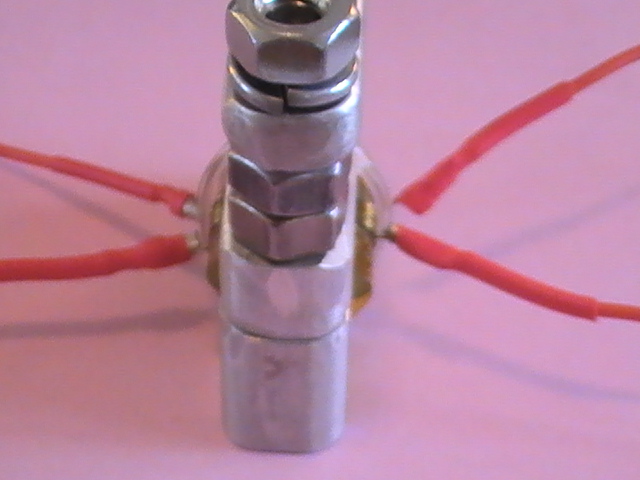
 Figure 2: Release Assembly |
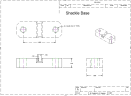
 Figure 3: Shackle |
Key parts of the device are (click on pictures to see higher resolution images):
- Shackle - (the gray and red in Figure 1 above).
- Mounting bracket - (blue)
- Heating elements - (yellow with red center, only one visible)
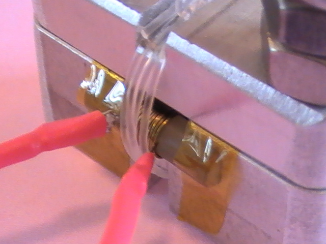
As shown in figure 2, the fishing line is wrapped vertically around the mounting bracket and shackle several times then tied. The channels cut into the mounting bracket and shackle keep the fishing line positioned over the heating elements and provide clearance so that the fishing line and its knot may slide and unwrap if some, but not all the wraps are cut by the heating elements. The edges of the channels are chamfered to facilitate this sliding and eliminate sharp edges that may cut the fishing line prematurely.
One heating element is located on each side of he mounting bracket permitting attachment to redundant flight computers. Either heating element is able to free the shackle. The heating elements are pressed into slots that are cut into he sides of the mounting bracket and held in place with Kapton tape. The elements extend a little beyond the sides of he mounting bracket to provide good contact the wraps of fishing line and so that the fishing line will pull tightly against them when the wraps are bearing the weight of the rocket.
A loop in the parachute tether is fastened to the shackle (figure 3). This loop is located between the drogue parachute and the main parachute's deployment bag. During steady drift, a force equal to the weight of the rocket is applied by he drogue parachute against the shackle. The wraps of fishing line bear this force and prevent deployment of the main parachute. The pins at the bottom of the shackle fit into holes in the mounting bracket and prevent the shackle from rotating.
When the fishing line wraps are cut, the drogue parachute pulls the shackle and the main parachute out of the rocket, deploying the main parachute.
The Heating Elements
We performed several experiments to translate the requirements of the release device to characteristics of the heating elements. Our goals were to:
- Reliably cut through the fishing line in less than 10 seconds.
- Power and control the heating elements directly from standard flight computer pyro outputs.
- Be inexpensive and easy to make so that the elements are disposable after one use.
- Provide for quick and easy removal of old heating elements and installation of new heating elements in the device without the need for machine shop tools.
The higher the power dissipation of the heating element, the faster it would cut through the fishing line. But, the power able to be supplied to the element was limited by the power ratings of the components used in the flight computer and the batteries. We estimated that the maximum power that the flight computers could handle was 30 watts. We built a 1.6 ohm heating element from insulated 2.6 ohm/ft resistance wire. We connected the element to a lab power supply and then operated it at different voltages while measuring how quickly it melted the fishing line.
| Voltage | Element Resistance | Power | Release Time (sec) |
|---|---|---|---|
| 7 | 1.60 | 31 | 3 |
| 6 | 1.60 | 23 | 4 |
| 5 | 1.43 | 17 | 4 |
We used the same heating element for all of the above tests. During the last test, we noticed that the resistance of the element had dropped to 1.43 ohms. This was probably due to the enamel insulation burning off the wire and a couple wire wraps shorting together.
We were please to observe that heating element power below 20 watts was able to sever the fishing line in less than half of our required time. This power level was well within the ability of our flight computers to control directly. However, we doubted that the Alkaline batteries that we were using could supply sufficient power to the heater. The Lithium Ion Polymer batteries that we were in the process of characterizing were demonstrating they had more than enough energy and current capacity to power the heaters. (Li-Ion/Polymer Battery Study)
We designed the heating element prototype to be powered from a 7.4V 800mAh (10C) Li-Po battery. This battery provides about 8.4V when fully charged. We wrapped a 3/16" wooden dowel with Nikrothal-LX .013" dia. enamel insulated resistance wire (6.124ohns/ft) to set the resistance of the heating element to about 4 ohms. The element was mounted in the Release Device, the shackle was inserted, and the device was wrapped with four turns of 60-lb. test fishing line. A Type-K fast response thermocouple was placed between the fishing line and the element. About a pound of tension was applied to the shackle, we began recording temperature, and switched on a 7.2-volt lab power supply. (7.2 volts was selected to model the voltage actually applied to the heating element when a fresh Li-Po battery is connected to the flight computer.) At this voltage, the heating element generated about 13 watts.
The heating element climbed to 250 degrees F in less than 5 seconds and melted the fishing line. As the shackle pulled free, power to the heating element was interrupted for about a second. Power was reapplied and the temperature of the heating element continued to climb. Twenty-one seconds into the test, the element reached 700 degrees and the wooden dowel caught fire.
From this test, we decided:
- The design was viable.
- 11 tightly placed turns of insulated resistance wire produced a heating element with physical dimensions that were ideal to heat 4 adjacent strands of fishing line.
- With a fresh Li-Po battery, the shackle should still be released in about 5-seconds.
- By setting the flight computer to power the heating element for 10-12 seconds, we would provide a 2x time safety margin and a 2x temperature safety margin for cutting through the fishing line.
- The wood core of the element needed to be replaced with a more flame resistant material. We decided to use G-10 glass rod for future tests.
Flight Testing the Device
My DragonFire2 rocket was modified to flight test the release device. Please select this link to see more application and flight test data on the release device.
Gallery
 |
 |
 |
Specifications / Drawings
 |
 |
 |