Super-ARLISS
| Rocketry Home |
| Feretich Home |
 |
 |
 |
Super-ARLISS - (2007-2008)
This is a two-stage rocket, where the sustainer stage can be used a standard ARLISS rocket to deploy university student payloads at an altitude of 10,000 ft. When launched as a two-stage rocket, its goal is to deploy university student payloads at an altitude of 30,000 ft. This is a joint design
project with Grant Saviers. We hope it will enable a 30,000 ft. ARLISS altitude bracket by significantly reducing the cost for both the students and fliers.
The ARLISS rocket program (www.arliss.org) is widely supported by both universities and rocketeers. Ten universities from around the world and over twenty rocketeers participated in the 2007 ARLISS event. The university teams provide the payloads/satellites to be deployed and the rocketeers provide rockets that are built to the ARLISS specification to deploy these payloads at the 10,000 ft. target altitude. The cost to the students is the cost of their payload device plus about $300 for propellant. It costs the rocketeer about $1500 to build a rocket to the ARLISS-M specification.
Being able to deploy student payloads at 30,000 ft. AGL (34,000 ft. above sea level when launched from the Black Rock, Nevada launch site) would allow student payloads to explore the boundary between Earth's Troposphere and Stratosphere. At that altitude, the air pressure is only 26% of normal and the temperature is about 100 degrees F colder than at ground level. However, the cost of powering a single stage rocket to this altitude is 6-times higher than a standard ARLISS flight and such a rocket would be an even bigger investment for rocketeers.
The goal for the Super-ARLISS project is to design and build a rocket that could be used for both the existing ARLISS program (10,000 ft. deployment and meet the ARLISS-M specification) and for a potential future ARLISS 30,000 ft bracket. By using a rocket of this design:
- The incremental cost to ARLISS rocketeers to support a 30,000 ft. bracket would be much reduced.
- The standard ARLISS motor reload would be used to deploy student payloads at 10,000 ft.
- The cost of deploying student payloads at 30,000 ft. would be only 3 times the cost of the 10,000 ft.
This is a two-phase project. The first phase (completed in 2007) was to design the sustainer stage of the rocket. The sustainer stage was used successfully by itself for standard ARLISS flights during the 2007 ARLISS event. It also served as a Level 3 certification project.
We are now in the second phase of the project. We are building the rocket's the booster stage. We also need to reconfigure the sustainer stage for two-stage flight. For standard ARLISS flights, the rocket separates into three independent sections. Each section is brought to ground by its own parachute. While this is tolerable for a 10,000 ft. flight, recovering three sections that deploy their main parachutes at 30,000 ft. is a serious problem. We decided to tether the sustainer stage sections together and bring it down using a dual deployment strategy. A set of drogue parachutes will deployed at apogee and the single main parachute will be deployed as the rocket descends below 1000 ft.
The sub-projects of phase 2 are:
- Development and testing of the main parachute release device. This device is required because we need to deploy all the parachutes from one parachute compartment and the main parachute must be retained in the compartment while the drogues are being deployed. More information on this project is available by clicking on the above link. Status: complete.
- High power battery characterization and selection. It is our desire to make a days worth of flights on the same battery pack without replacement/recharging. We also needed to supply the main parachute release device with its higher than normal power requirement. Status: Complete.
- Igniter characterization. We need a way to ignite the sustainer motor while it was airborne. The ignition method has to be responsive and reliable. Status: On-going.
- Drogue parachute configuration testing. The tethering together of the sustainer sections results in increased possibility of entanglement and collisions between airframe sections. We especially need to ensure that the student payload is deployed without it colliding or entangling with sustainer sections. We believe that the configuration of drogue parachutes that we will use should prevent such occupancies.
Updates:
10-11-08 Added the flight results from the Mavericks and ARLISS/XPRS launches.
5-17-08 Flight tested the main parachute release device.
3-20-08 Completed the high power battery characterizations.
9-18-07 Phase 1 complete! Updated flight status, added pictures to gallery, short fin drawing, and Flight Results section.
9-09-07 Updated the design spec document and added
9-04-07 Added RockSim and stability calculation worksheet
8-30-07 New sustainer avionics schematic shows new LED circuits, BeeLine GPS, and RF caps.
8-30-07 Added avionics bay pressure equalization port calculations worksheet.
Specifications:
Diameter: 6"
Length: Sustainer
100", Booster 69.825"
ARLISS Mass: 19.5 Kg (43 lbs.) including M1419 motor, but no payload.
Two-stage Mass: 30 Kg (66 lbs.) without motors.
Status: The sustainer stage was flown multiple times in its ARLISS configuration at the AEROPAC ARLISS event at Black Rock, Nevada, Sept. 12-14, 2007. Both Grant's and Bob's rockets flew well and earned them Level 3 Certifications.
2-stage launch planned for July 18th Mavericks event.
Design Specification (Ver. 1.1) - Level 3 project specification (not updated with latest 2-stage mods.)
Detailed Drawings:
| ARLISS Configuration Assembly (8/25/07) | Sustainer Assembly
|
Booster Assembly (two stage flight) Upper Airframe (4/23/07) Lower Airframe (4/23/07) |
| Sustainer Section Components: | ||
|
Avionics Bay |
Avionics Bay continued... |
Body Tubes |
| Main Parachute Deployment Device | Fins (9/18/07) We used shortened fins on the sustainer. |
|
ARLISS Stability Calculations |
Payload Carrier (J. Coker's 3/29/07) |
|
| Booster Section Components: | ||
Booster Upper Airframe (6/23/08) Booster Lower Airframe (6/23/08) |
Avionics Assembly (7/15/08) | Electrical Schematic (tbd) |
Interstage Coupler, Sustainer(7/15/08) Interstage Coupler, Booster (6/23/08) |
Std. ARLISS Fins (T. Rouse's 3/4/07) |
AeroPack Motor Retainer |
| Common Components: | ||
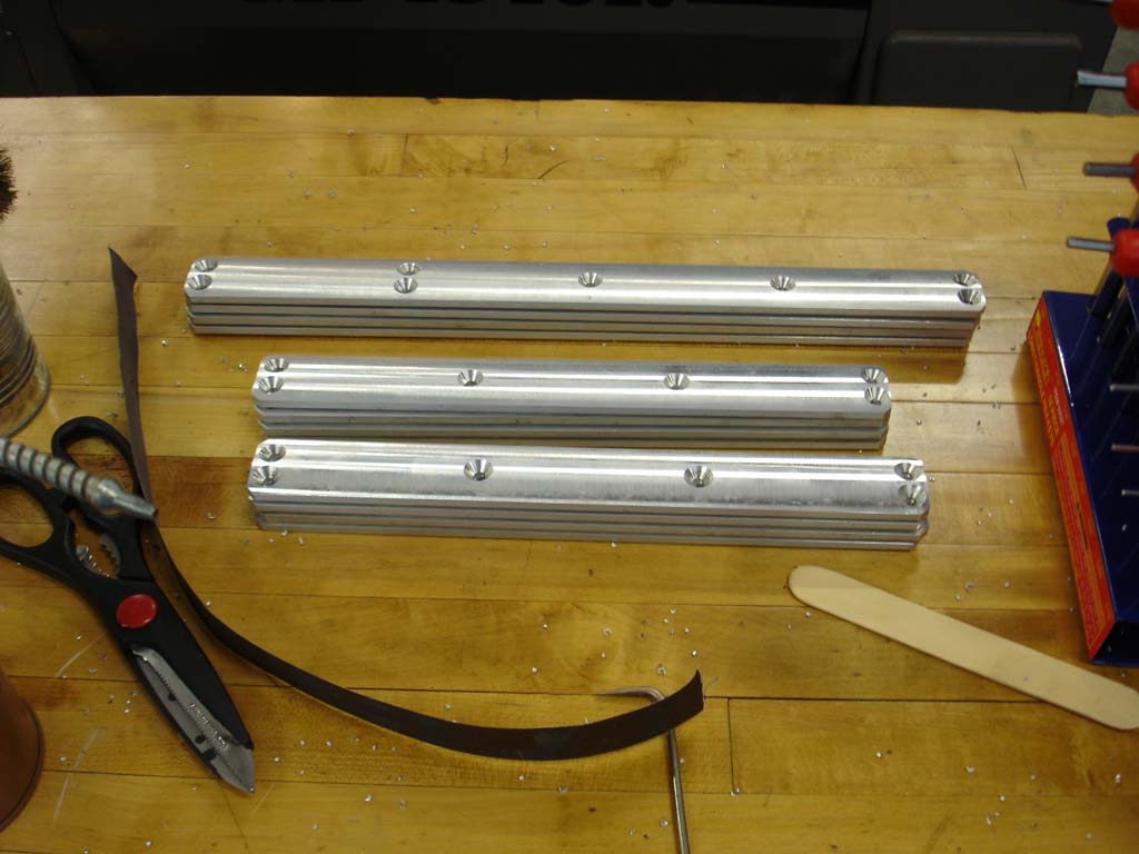
| Fin Frame Assemblies (4/24/07) | Fin Frame Bars (4/25/07) | Top Fin Frame Centering Ring (8/14/07) |
| Sustainer Aft Fin Frame Centering Ring (6/23/08) | Booster Aft Fin Frame Centering Ring |
Fin Frame
Screws (rated 144,000 psi) |
| Main Parachute Swivels (rated 850 lbs) |
Drogue Parachute Swivels (rated 600 lbs) |
Motor Eye-Bolt |
ARLISS/XPRS 2007
Flight Results:
- Even though we used Aluminum in most bulkheads, centering rings, fin frame, and fins; this design was lighter than most ARLISS designs.
- All flights were straight up with no wobble or wind cocking. The precise alignment of the fins achieved by the CNC machining and the rigidity of the aluminum fin frame is credited.
- We flew the combined "Level 3 Certification" and "new ARLISS rocket certification" flight without a student payload. Without the payload, the rocket was stable by about .75 diameters, according to the worst case RockSim calculation method (Barrowman). So we decided to attach about 3.5 lbs of weights to the nosecone internal bulkhead. After flight examination of both rockets showed signs of stress on the nosecone collar. It was probably caused by the high inertia of the weighted nosecone during payload carrier ejection. The weights were removed for subsequent flights and no additional stress signs were found. Just to be safe, we plan to reinforce the nosecone collar before the next launch event.
Bob's MC2 Flight Profile
Grant's MC2 Flight Profile - The redundant avionics succeeded in deploying the parachutes and payload carrier on time, but Bob was unable to upload the G-Wiz MC2 flight profile on his second flight. The altitude at apogee reports from the computers varied wildly. The Bob's first flight, the MC2 reported an integrated apogee at 11,553 ft and a barometric apogee of 9,407 ft. While the LCX beeped out an apogee of 13200 ft. There is a known bug in the MC2 & LCX altitude tables and the firmware for these computers need to be upgraded for more reliable altitude calculations.
- In general we found that it took too long for us to "turn-around" the rocket (cleaning after a flight and preparing for the next flight). We plan to make several modifications to help turn-around. Initial thoughts are...
- Be able to turn on/off the GPS transmitter without removing the avionics bay from the rocket.
- Be able to recharge or replace the avionics logic batteries without having to remove the bulkheads from the avionics bay.
- Have a motor/CD3 cleaning station setup at or near our camp.
- Bring strap wrenches to tighten/loosen motor closures.
- Load disposable CD3 match holders with black powder the night before the launch.
Mavericks 2008
Changes made for his launch
The Mavericks launch was chosen for our first attempt to launch the Super-ARLISS in its 2-stage configuration. To prepare for this launch we made the below changes:
- We changed our plans for the interstage coupler from "a sleeve surrounding the end of the sustainer motor" to "a boat-tail machined to a self-releasing taper". This design would keep the two stages joined as long as the booster's thrust benefited sustainer, then separate at the moment the booster's drag attempted to slow the sustainer.
- Since we expected the new design to drag separate when the booster motor burned-out, we needed to use the sustainer flight computers to ignite the sustainer motor rather than the booster's flight computers.
- Constructed the booster stage as described in the above drawings.
- Added the Main Parachute Release Device to the sustainer's lower avionics bulkhead.
- Added a 1.9" diameter rolled paper tube to fit over the sustainer's parachute compartment CD3 unit to bypass ejection gas around the main parachute.
- Modified the sustainer's avionics bay to hold and be powered from four Lithium-Ion Polymer batteries. These batteries could power the flight electronics for over eight hours, permitting multiple launches per day without recharging. The also provided the power needed to operate the Main Parachute Release Device. The new design permitted all batteries to be recharged without disassembling the avionics bay.
Mavericks launch results
The launch took place on Saturday, July 19, 2008. The rocket was carrying a 2-kg payload in a carrier just below the nosecone. Visibility was excellent. Ground level winds were light. Unknown to us at the time, winds aloft were blowing from the south at 50 knots. The Super-ARLISS, in its 2-stage configuration, was loaded with a N2000 (booster) and a M750 (sustainer). The sustainer motor was set to ignite 8 seconds after booster burnout. The flight was simulated to reach 27,500 feet.
We observed that the booster lift-off went well. Shortly after booster burnout the sustainer separated from the booster. As the sustainer was coasting, it weathercocked significantly into the wind. When the sustainer motor fired, the sustainer was about 40 degrees off vertical. The sustainer motor ignited at about 10,000 ft AGL and flew directly over the flight-line heading up and to the south. The sustainer continued to climb and disappeared from sight. Both the booster and sustainer contained BeeLine GPS transmitters, and both transmitters broadcasted their positions while they were airborne.
After the booster separated from the sustainer, it deployed its parachutes. The booster was to be recovered via a 10-foot parachute. At booster apogee, a 3-foot heavy-duty (Pro-Exp) drogue parachute was deployed. The drogue parachute was attached to the deployment bag that contained the main parachute. It was expected that this arrangement would permit the drogue parachute to orient and stabilize the booster before the main parachute inflated.
At booster parachute deployment, the drogue parachute and the main parachute deployment bag ripped free and floated away to the north. The main parachute never appeared to inflate. The booster came down fast using the uninflated main parachute acting as a streamer.
First we drove out and recovered the booster. It was recovered about 1/2 mile north of the launch pad. We verified that the drogue parachute and deployment bag had detached and were missing. All of the main parachute panels had ripped out approximately 2 inches from each seam. (All seams were intact.) All four fins were severely bent.
The sustainer was to deploy a 3-foot heavy-duty drogue parachute at apogee and then deploy the 12-foot main parachute at about 1000 feet AGL. We recovered the sustainer about 2.5 miles south of the launch pad. The main parachute was still in its deployment bag and the deployment bag was only half way out of the parachute compartment. I reached down and pulled on the main parachute's deployment bag. It took only a couple pounds of force to pull it free of the parachute compartment. The nosecone and payload were missing.
| For launch photos see the Mavericks 2008 Event page. |
| Sustainer Flight Data | Booster Flight Data |
|---|---|
| MC2 #1 Flight Computer gwiz pdf | LCX #1 Flight Computer gwiz pdf |
| MC2 #2 Flight Computer gwiz pdf | LCX #2 Flight Computer gwiz pdf |
| BeeLine GPS Log kml pdf | BeeLine GPS Log kml pdf |
Analysis of the recorded flight data showed:
- One booster flight computer detected apogee and attempted to deploy the parachutes at 8,300 ft. The other booster flight computers detected apogee and deployed the parachutes at 4,400 ft. From simulation and observation the booster actually achieved apogee at about 8,000 ft. We believe that one flight computer prematurely deployed the parachutes while the booster was moving upward at a high rate of speed resulting in the drogue parachute being ripped free and the main parachute being shredded. We also believe that the flight computer was fooled because its barometric sensor was reading the turbulence caused by the fins of the sustainer stage.
- The sustainer apogee occurred at about 22,500 ft AGL. Apogee occurred at a distance of 31,500 ft from the launch pad. (Using some basic trigonometry, we calculate that apogee occurred 22,000 ft south of the launch pad.)
- The sustainer flight computers detected a -17G acceleration event at apogee. We believe that the large magnitude of this event was due to the high horizontal velocity caused by weather-cocking. This event tore the payload loose from its straps and sent it out the top of the rocket. The force of the payload knocked out the nosecone.
- The sustainer descended on its drogue parachute at 87 ft/sec.
Flight post-mortem
Things that worked well:
- Sustainer avionics and lower airframe survived a drogue only descent without damage.
- Li-Po batteries performed as expected. Voltage after recovery:
Logic=8.1V, Pyro=8.3V. - The sustainer avionics worked as designed.
- The sustainer drogue parachute (3 ft. Rocketman Pro-X) and tethers survived the 17 G deployment event.
- Interstage coupler worked perfectly. Stages drag separated. (Much of the drag may have been caused by the premature deployment of the booster's parachute.)
- Entire booster airframe survived a "streamer" descent, with only bent fins.
- The booster avionics compartment and flight computers survived. (The GPS unit was damaged.)
- The pyrodex igniters worked as designed. I believe that the optimal formula is one 50/50 pellet per 98mm grain. The N2000 uses 6-grains. I only used four pyrodex pellets and it still worked, though ignition was as slow igniting as when we use commercial igniters.
- The GPS transmitter allowed us to find the sustainer quickly.
- The main parachute release device seemed to work properly. (Even though the deployment bag did not fully exit the rocket.)
- The sustainer reinforced fins worked well, even at Mach 1.1.
|
|||||
|
|||||
|
|||||
Things that need improvements:
- The sustainer avionics top bulkhead needs to be redesigned.
- Poor wire management caused final assembly problems.
- The battery terminals interfered with the eye-bolt.
- The battery terminals were too small for the surge current capability of the batteries.
- The CD-3 terminals were too close together to use knurled nuts.
- The battery hold down eye-bolts deformed the sides of the Li-Po batteries.
- The batteries interfered with being able to place a box-end wrench on the threaded shaft nuts.
- Power switches for the GPS units would be nice. Now, the GPS transmitter must be turned-on before the avionics (AV) bay is loaded into the rocket.
- Need jumper cable to upload flight computer data without AV bay disassembly. This would permit faster flight turnarounds.
- The sustainer CD-3 gas bypass tube was crushed. The crushing probably occurred in final assembly. The crushing did not seem to effect its performance on this launch, but it should be rebuilt stronger and of a shape which uses less parachute compartment cross-sectional area.
- The sustainer deployment bag got stuck in the airframe. The fit was probably too tight given the large cross section CD-3 gas bypass tube. The fit must be made to allow the main chute d-bag to fall out. Perhaps a larger drogue parachute is needed to create more extraction force.
- The booster hard landing severed the battery hold-down wraps, destroyed the Duracell 9V batteries, snapped the corner off the BeeLine GPS circuit board and bent all four fins. Since the impact was well beyond specification, I don't believe we need to address these items.
- Plans for future coast phases of the sustainer need to take into account the Jet Stream. A much shorter sustainer ignition delay would have been better.
ARLISS/XPRS 2008
Changes made for this event
The first four days of this event are dedicated to the ARLISS university program. Our plan was to fly the sustainer several times during this portion of the event. Then, provided that the Super-ARLISS sustainer was survived undamaged, the Super-ARLISS would be launched on the fifth day in its 2-stage configuration. To prepare for this launch we made the below changes:
- Due to damage received at the Mavericks flight, the nosecone, sustainer upper body tube, and booster fins were replaced.
- The method of retaining the sustainer's avionics bay in the body tube was changed. The avionics bay was retained by a 1/4-20 rail button screw and four 8-32 flange button head machine screws. This remains the same, but now all these screws are mounted in the aluminum lower bulkhead. This change simplified assembly.
- The top avionics bulkhead was redesigned. An ABS plastic battery holder was added to protect the batteries. The avionics spacer coupler now attaches to this battery holder. This eliminated the wire management issues experienced at the Mavericks launch. Battery terminals were upgraded to use higher current locking connectors. CD-3 e-match terminals were moved farther apart. The eye-bolt was repositioned to provide better clearance.
- GPS is now cushioned from shock by a block of foam.
- Jumper cables were made to permit flight computer data uploads without AV unit disassembly.
- The gas bypass tube was redesigned to use PVC tubing. Its diameter and position were also changed to permit more parachute room.
- The sustainer's 3 ft heavy duty drogue parachute was replaced with a 4 ft heavy duty (Pro-Exp) drogue.
- The booster parachute rigging was redone to not rely on the strength of the deployment bag loops. One of these loops had ripped off during the Mavericks flight.
- The flight computers were reprogrammed to ignite the sustainer motor 1 second after booster motor burn-out.
- The booster flight computers were programmed to use accelerometer measurements rather than barometric pressure to detect apogee.
|
|||
|
|||
|
|||
|
ARLISS/XPRS launch results:
During the ARLISS portion of this launch event, the Super-ARLISS was flown three times in its single stage configuration to deploy student satellites at about 10,000 feet. All three flights were flawless.
The Super-ARLISS was then reconfigured for two-stage flight. This consisted of:
- Replacing the Aeropac motor retainer with the interstage coupler boat-tail.
- Replacing the three ARLISS parachutes with the dual-deploy 12-foot main parachute and 4-foot drogue. The Main Parachute Deployment device was also armed.
- The CD-3 gas bypass tube was inserted.
The 2-stage launch took place on Saturday, September 20, 2008. Visibility was good. Ground level winds were moderate and from the southwest. Winds aloft were reported to be very light. An accelerometer instrumentation payload was prepared and inserted. Since this payload was designed to be carried inside the rocket for the entire flight, the payload ejection mechanism was disabled. The Super-ARLISS was loaded with a N2000 (booster) and a M795 (sustainer). The sustainer motor was set to ignite 1 second after booster burnout. The flight was simulated to reach 26,200 feet.
We observed that the booster lift-off went well, except for some slight weather-cocking. The weather-cocking matched that observed for other rockets that were launched shortly before and after it. Shortly after booster burnout the sustainer separated from the booster. When the sustainer motor fired, the sustainer was about 20 degrees off vertical. The sustainer motor ignited at about 7,000 ft AGL. and flew on the 20 degree trajectory to the southwest. The sustainer continued to climb and disappeared from sight. Both the booster and sustainer contained BeeLine GPS transmitters, and both transmitters broadcasted their positions while they were airborne.
After the booster separated from the sustainer, it deployed its parachutes and drifted slowly to the north. We drove out and recovered the booster. It was recovered about 1/2 mile north of the launch pad. Both the drogue and main parachutes had deployed. No damage was visible.
We followed the GPS tracking data to the sustainer. It was recovered 3.5 miles northeast of the launch pad. Both the drogue and main parachutes had deployed. No damage was immediately visible.
| For launch photos see the ARLISS/XPRS 2008 Event page. |
| Sustainer Flight Data | Booster Flight Data |
|---|---|
| MC2 #1 Flight Computer gwiz pdf | LCX #1 Flight Computer gwiz pdf |
| MC2 #2 Flight Computer gwiz pdf | LCX #2 Flight Computer gwiz pdf |
| BeeLine GPS Log kml pdf | BeeLine GPS Log kml pdf |
Analysis of the recorded flight data showed:
- The booster flight computers detected apogee and deployed the parachutes at 6958 ft. (The two booster flight computers agreed to the foot!)
- The sustainer apogee occurred at about 24,800 ft AGL. Apogee occurred at a distance of 35,000 ft from the launch pad. (Using some basic trigonometry, we calculate that apogee occurred 24,700 ft southwest of the launch pad.)
- The sustainer flight computers detected a -24G acceleration event at apogee. This payload was better secured and lighter than the Mavericks payload. The event did not eject the payload from the rocket.
- The sustainer descended at 31 ft/sec. Both sustainer flight computers stopped recording 5000 ft. AGL. This rate of descent was substantially slower than the calculated drogue descent rate (~58 ft/sec) and faster than the calculated main parachute descent rate (~24 ft/sec).
- The payload contained two 2-axis accelerometers. They were oriented for double coverage on the vertical axis. Close examination of this accelerometer data showed that the -24G accelerometer event mentioned above actually consisted of two separate deceleration events of similar magnitude separated by about one second. The displayed time scale used by the G-Wiz flight computer software was too compressed to distinguish a one-second interval. Dumping and examining the raw flight computer data verified the two events.
After we returned from the playa, examination of the rocket components revealed:
- The 10-foot main parachute had three small rips in the center of one panel. Each rip was about 4 inches long and were separated by about an inch. There were also small (2-inch) rips in the bottom corner of that panel and one other panel.
- One booster fin was slightly bent.
- There was a deep notch (1/4") in the leading edge of one sustainer fin and a slight notch in the leading edge of an adjacent fin.
Our conclusion is that once the sustainer was out of sight, it continued to arc over and developed substantial horizontal velocity. Deployment of the drogue parachute caused a -24G event that caused the premature deployment of the main parachute. The main parachute deployment device retains the main parachute using four wraps of 60# test fishing line designed to resist a shock 13Gs. The main parachute's deployment bag was pulled out of the airframe, the main parachute was pulled out of the bag, and it opened one second after the drogue parachute. The opening of the main parachute caused the second event (near -24Gs), which resulted in the small rips.
We don't know what caused the notches on the sustainer fins. They were not noticed until we returned from the playa. They could have been caused while transporting the rocket home.
Flight post-mortem:
Things that worked well:
- Everything that worked well at the Mavericks launch worked well again at his launch.
- The sustainer avionics attachment method and top bulkhead redesign made sustainer final assembly much easier. All of the problems detected at Mavericks launch were eliminated.
- The jumper cables permitted easy upload of the flight computer data without disassembly of the avionics bays.
Things that need improvements:
- Power switches for the GPS units would still be nice.
- We calculated the horizontal velocity at apogee to be about 200 ft/sec. It seems that this magnitude horizontal velocity at apogee is common for flights of this type. Inflation of the sustainer’s drogue parachute should be made to occur more slowly so that deceleration is not so severe. We should also consider switching back from the 4-foot drogue parachute to a 3 foot drogue.
- The Main Parachute Deployment Device should be upgraded to withstand greater deceleration events.
Project conclusions
We were very satisfied with the Super-ARLISS flights at ARLISS/XPRS 2008. We proved that an ARLISS-M rocket could be designed to function well for official 10k foot student payload flights and fly as a second stage to bring payloads to significantly higher altitudes. However, we fell short of our 30,000 foot altitude goal. We believe we could have achieved very near 30,000 feet if both ground level and high altitude winds were very low, but it would be impractical to expect these ideal wind conditions to exist throughout multi-day university launch events. We also discovered that preparing a two-stage rocket for launch is more than twice the work and has more than twice the potential for catastrophic mistakes than preparing a single stage rocket. The increased complexity and work would probably be a significant barrier to rolling out an ARLISS-like program based upon 2-stage vehicles.
Gallery:
 We decided to have the body tubes shipped uncut from PML. |
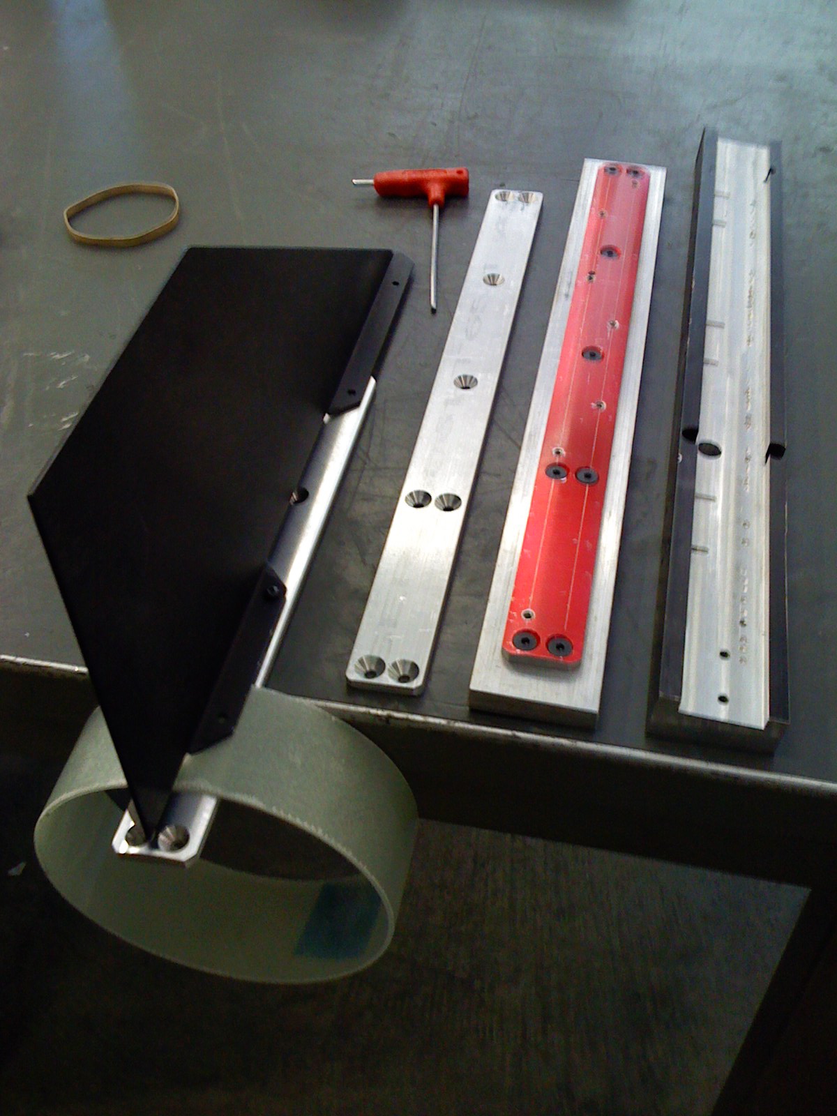
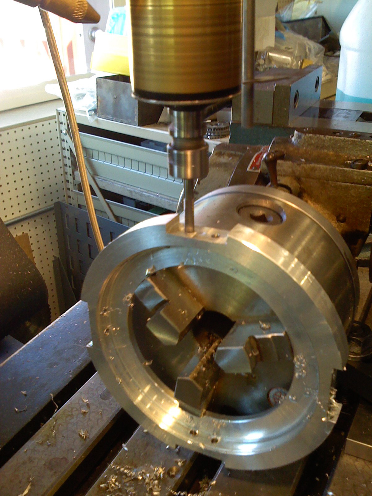
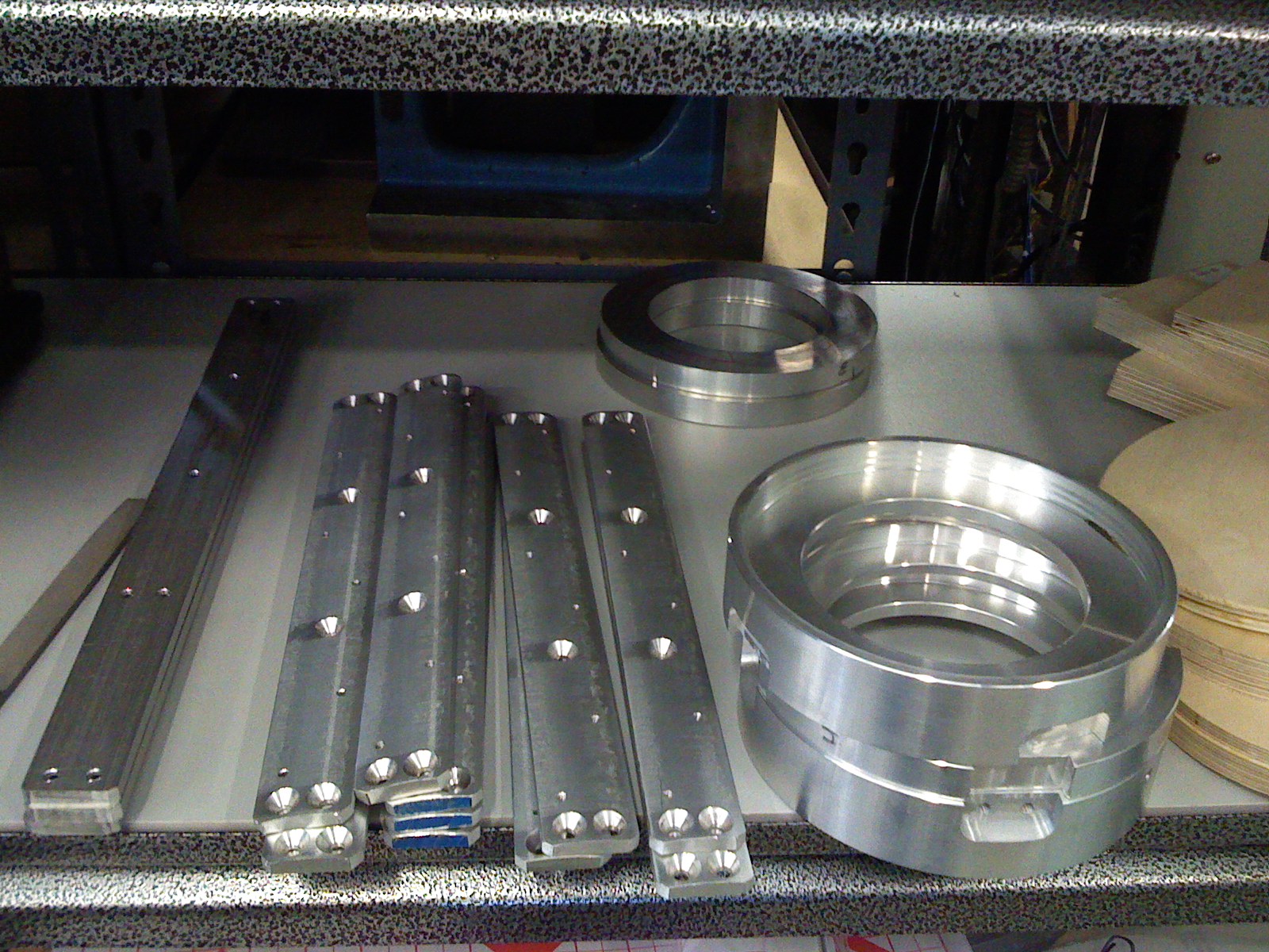
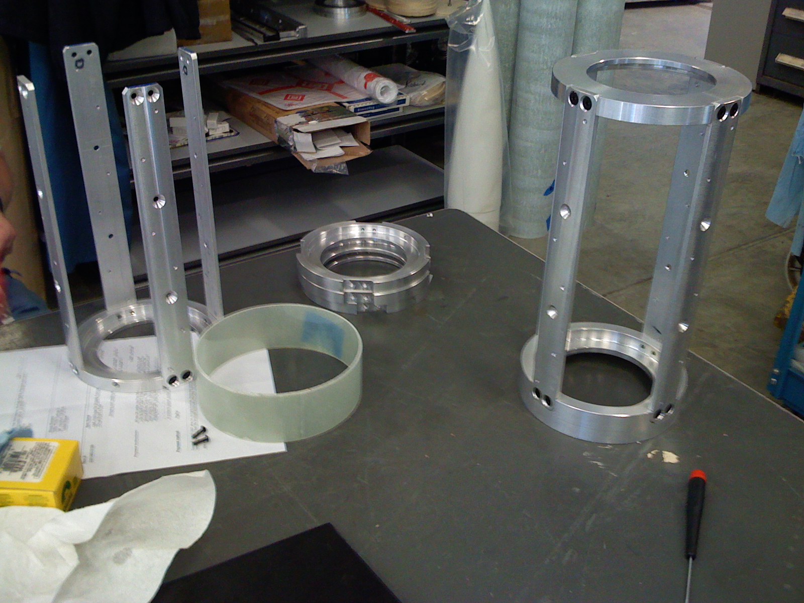
 Couplers and payload carrier components |
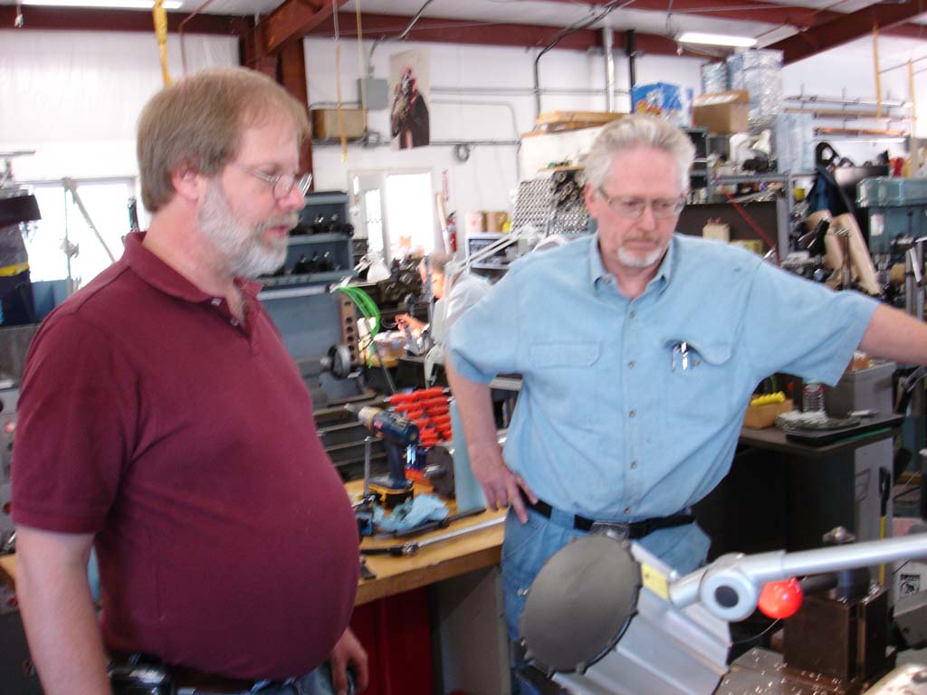
 Grant making brackets for the cutting table |
 The tube cutting table. The original design for this table was borrowed from John Coker. We improved upon it by adding a single point tube fence to keep the distance to the saw blade constant during the cut. |
 Grant is measuring tube wall thickness. We found that the wall thickness was reduced near the ends of the tube. We cut about 6" off the ends to get to the specified .080" thickness. |
The tube cutting table was a very good investment. All tube cuts were precise and were able to be performed quickly. We made single point fence adapters for body tubes, fiberglass couplers, phenolic carriers, and a tube extender to cut rings from small pieces, |
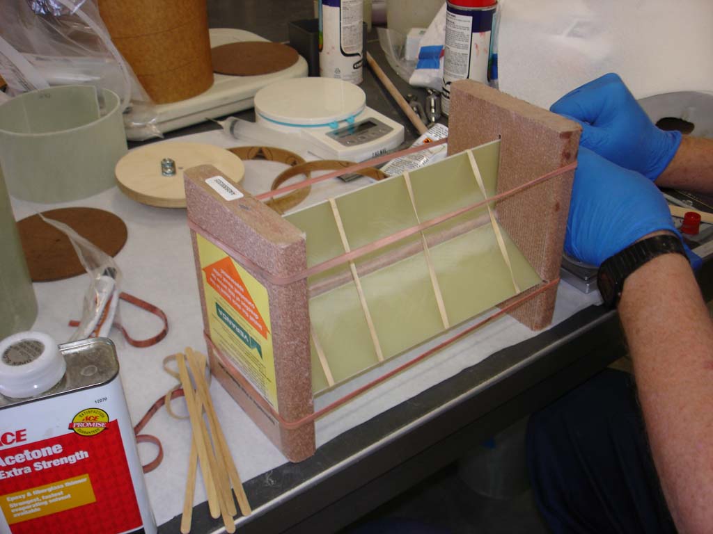 |
The jig used to make payload carrier dividers. Our payload carriers have a removable divider to convert from "open class" to triple "soda can satellite" operation. |
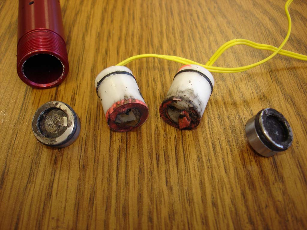 |
Photo of used "disposable CD3 e-match holders" after parachute and payload carrier ejection testing. They are made of Delrin and permit us to glue e-matches into the holder before we depart for a launch event. |
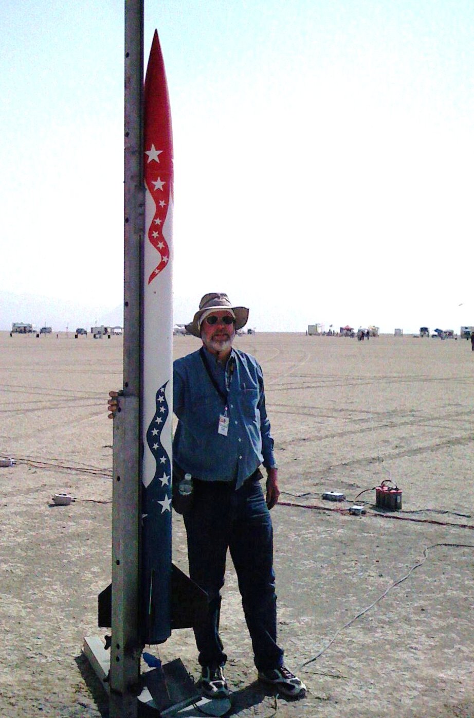 |
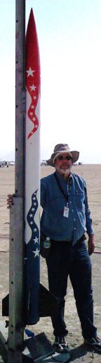
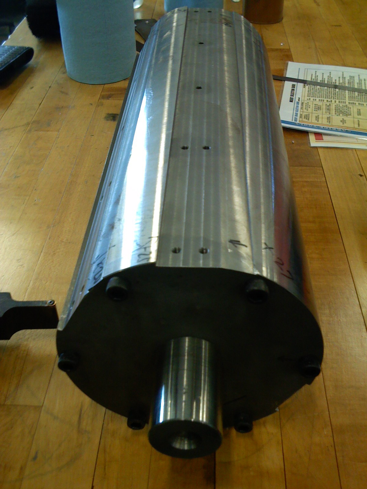
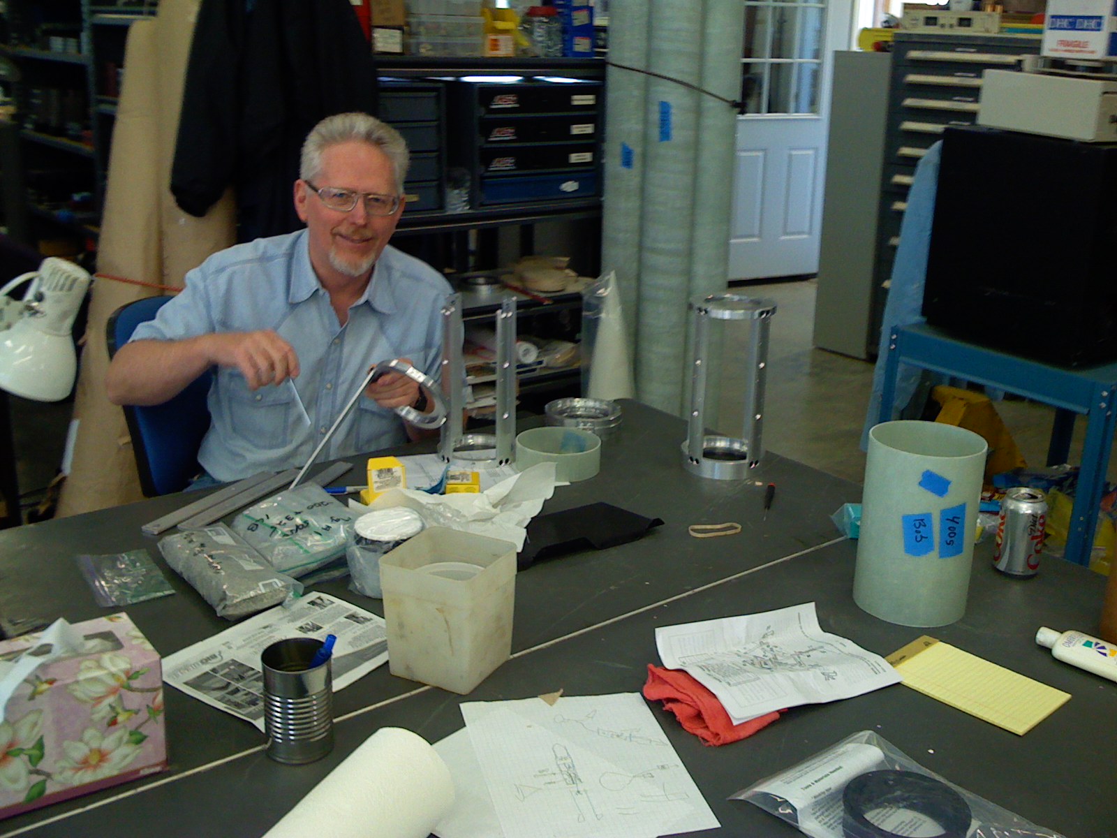
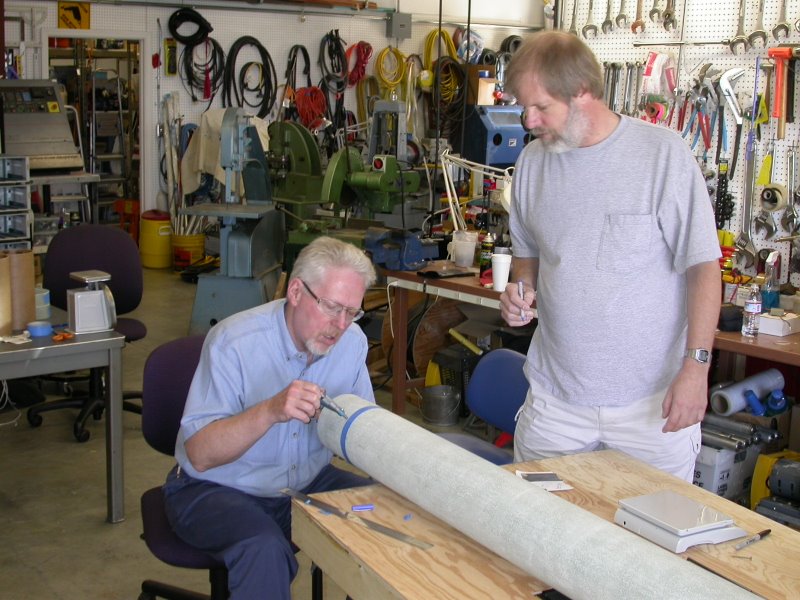
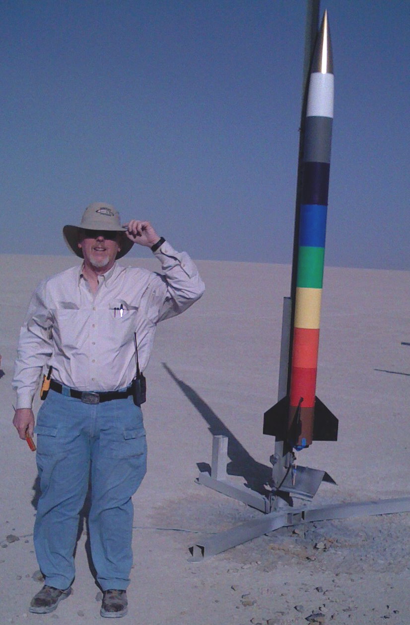
Bob posing with his Super-ARLISS sustainer stage (top). |
 |