Totally Stable
(Attitude Stability Unit (ASU) Test Rocket)
| Rocketry Home |
| Feretich Home |
 |
Totally Stable - (2010, 2011)
This rocket was designed to be a test vehicle for the Attitude Stability Unit (ASU), which is described in my web site's Resources section. Aspects of the rocket that are closely tied to the ASU are discussed on that page. This page is focused on the test rocket and its aerodynamics.
Goals:
The goals for the rocket are:
- Accommodate testing of the ASU.
- Be able to support Mach 1.8 flights using 98 mm N2000 or similar motors. Flights with this class of motor is anticipated in the later stages of ASU testing.
- Support testing at lower speeds and altitudes using less expensive 54 mm motors like the K550.
- Be able to survive and safely return to earth even when experiments produce unexpected results. This goal emphasizes the durability and recovery safety margin in the design. The rocket must be designed to provide safe recovery even when parachute deployment occurs at high velocities. Such a deployment must not cause shredding or detachment of the parachute and the rocket body must be very difficult to zipper.
- Provide the ability to taylor the rocket's rear fins to the needs of a specific flight. That is, the rockets rear fins should be easily replaceable with fins of a different style or size.
- The rocket must not add unneeded risk to the flight. The ASU is a very complicated device and it should dominate the risk aspect of the flight. Therefore the test rocket itself should be kept simple and not significantly increase the risk. This was the driving factor toward our choice to use simple versus dual deployment recovery mechanism.
- To save mass, the rocket avionics electronics and power will share space and power with the ASU. (The implementation packages the flight electronics inside the ASU and shares a common battery set.)
Specifications:
Diameter: 4" (actually the external fin can is ~4.25" OD)
Length: 102" with 54 mm boat-tail motor adapter
Mass: 6.98 kg (15.4 lbs) with the ASU, but without motor
CP position: 70" from nose.
CG position: Varies with motor, but has a 1 static margin with the worst case motor (M1939, N motors move the CG more forward).
Flight Computers: Two G-Wiz MC2s
GPS Transmitter: BeeLine GPS.
Status: Built, started flying in Sept. 2010.
The high thrust Mach 1.8 requirement drove us to select filament wound fiberglass as the body tube material and a fiberglass nose cone. The ASU was being designed to fit in a 4" dia rocket. So we searched for an economical way to gather the required airframe parts. We were able to adapt the Extreme Wildman Kit to our needs (the Wildman was able to substitute an unslotted 48" body tube for the 52" slotted body tube that came with the kit).
Lower Airframe:
We wanted the rears fins to be aligned perfectly straight with the rockets main axis and replaceable. Since the N-motor consumed all of the room inside the body tube we chose to use an external fin can. None of the commercially available external fin can units provided both of these features, so we decided to fabricate our own fin can. (See the below drawings.) We started with a length of thick walled aluminum tube, 5" OD and 3.5" ID. (All aluminum is 6061-T6 alloy.) We bored out the ID on a lathe to slide over the body tube. We then mounted the the fin can in an indexer on an end mill. Using the end mill we removed the external material leaving the a .090 wall and the fin mounting tabs. Making a cut with an standard end mill at 2 degree rotational increments yielded a reasonably rounded external surface. The final depth cuts in the nearest the fin tabs were made using a ball end mill to provide a fillet on the tab. The fin slots were made using an extra long 3/16" end mill. The wall thickness below the slots is .040" to promote flexing and provide a safe designated place for potential flexure stress fracture. The fin mounting screw holes were also close fit drilled, tapped, and countersunk on the indexer.
To handle the supersonic speeds without flutter we chose to make the fins from 3/16" thick aluminum plate. A simple flat plate fin design was chosen to minimize the work required to make alternative fins. Each fin fits into a fin slot on the fin can with only .001" space on a side. The 11 #5-40 screws (all screws are 70 psi stainless steel) that secure each fin flex the tabs so that the fins are held securely in the slots by both the shear strength of the screws and side friction from the tabs. The fins are a simple symmetrical trapezoidal shape with a 6" root chord, 3" tip chord, and a 4.1" span. A 5 degree bevel was applied to the leading and trailing edges
The external fin can was epoxied onto the lower body tube so that it extended 1" below the tube. (Aeropoxy ES6209 was used throughout.) The 1" space below the body tube was supplied for the 1/2" lip on the 98 mm motor aft closures and for a 1/2" ring to retain the motor. The 1/2" retaining ring is secured by four #8-32 flange button socket cap screws. One of these screws also holds the lower launch rail button.
A coupler with a slotted bulkhead was epoxied into the top of the lower body tube. The bulkhead is positioned 1" into the coupler, is made from 1/2" aircraft plywood and is captured between 1" wide G-10 rings. The bulkhead prevents the parachute from being pushed into the lower airframe, restricts ejection gas from entering the lower airframe, and strengthens the top of the lower airframe making it capable of handling high velocity parachute deployments without zippering. A small wood block with a #8-32 T-nut is epoxied inside the lower part of the coupler. The upper launch rail button is attached via this T-nut. There is just enough room below the bulkhead and above the eye-bolt of an N-2000 size motor case for a parachute tether knot. Two #10-32 flange button socket cap screws are threaded and epoxied into opposite sides the coupler about 1/8" above the top of the body tube. These screws fit into slots cut into the bottom of the upper airframe. These screws/slots prevent the upper airframe from slipping rotationally on the coupler and make the upper and lower airframes roll together.
Upper Airframe:
The nose cone and upper body tube are the ones provided in the Extreme Wildman kit. An ASU mounting ring was epoxied about 1-5/8" above the shoulder of the nose cone. The coupler part of the nose cone was slotted to allow the ASU to be slid into the nosecone so that the canard axils are aligned with the nose cone's shoulder. The upper body tube is then slid over the ASU, onto the nose cone coupler, and fastened to the bottom ASU bulkhead by four #10-32 flange button socket cap screws. The rockets flight electronics are housed in the ASU and described on its web page.
Detailed Drawings:
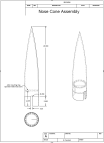 Nose Cone Assembly |
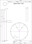 Upper Body Tube |
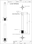 Lower Airframe Assembly |
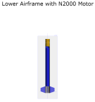 Lower Airframe 3-D |
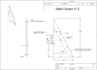 Delta Canard |
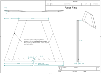 Rear Fin |
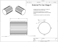 External Fin Can |
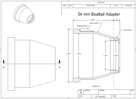 98 mm to 54 mm Boattail Adapter |
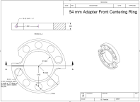 98 mm to 54mm Adpt Centering Ring |
Recovery system:
Parachute deployment is triggered by either of a pair of redundant flight computers firing a CD3 CO2 gas ejection device. The gas separates the upper and lower rocket sections and deploys the main parachute. The main parachute is a 6 foot Ballistic MACH 1 High Speed Parachute capable of being deployed near the speed of sound. The parachute is attached to the upper and lower airframe sections by heavy duty nylon tether and tied to forged steel eye-bolts. The tether knots are taped over with plastic electrical tape to prevent the knots from loosening. The upper airframe eye-bolt is attached to the bottom ASU aluminum bulkhead. The lower airframe eye-bolt is screwed into the motor's forward closure. All components in the deployment shock path are capable of withstanding more than 1500 pounds of force.
Gallery:
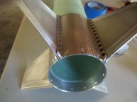 Fin Can (bottom view) |
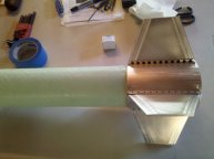 Fin Can (side view) |
Rocket Sections and the 98 mm to 54 mm Adapter |
Ready to Fly |
Rocket Aerodynamics:
The roll moment of inertia for the rocket have been measured using a Torsion Pendulum. See my Torsion Pendulum web page for a description of this device. The Roll Moment of Inertia (Ix) measured was 0.018705 Kg*m^2.
Aerodynamics is not my forte, so the below may be prone to misunderstandig and error. If you spot an error, please report it via my business contact page http://www.rafresearch.com/contact.html.
Canard or fin lift can be calculated from...
![]() (equation 1)
(equation 1)
The tricky bit is determining what Coefficient of Lift function should be used.
Lift for incompressible flow
The initial calculations of canard lift with respect to angle of attach for incompressible flow is based on Polhamus's method. Imcompressible flow applies when the rocket is traveling very flowly.
![]()
Our canards have an aspect ratio (AR) of 2. From the chart on page 12 of "Application of the Leading-Edge-Suction Analogy of Vortex Lift to the Drag Due to Lift of Sharp-Edge Delta Wings" we are able to determine our Kp=2.20 and Kv=3.20.
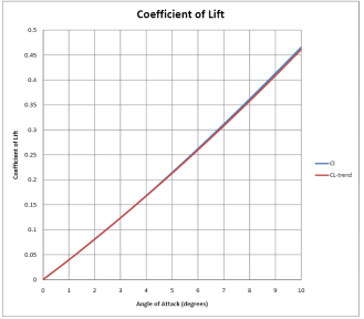
Plugging these constants and angles from 0 to 10 degrees into the above formula we produce the below lift chart.
The line on the chart is fit by the equation CLαI = .000479α^2 + .038879α (equation 2)
Lift for compressible flow
According to Flight Dynamics by Robert F. Stengel (pg 72), compressable lift slopes CLαc can be estimated from incompressable slopes CLαi by:
![]() ; where M is the Mach number the rocket is traveling at.
; where M is the Mach number the rocket is traveling at.
Note that at M near 0, the compressible flow coefficient equals the incompressible flow coessicient, so this equation can be applied at all subsonic speeds. Since the Aspect Ratio (AR) of the canards is 2.0;
![]() ; where M is the Mach number the rocket is traveling at.
; where M is the Mach number the rocket is traveling at.
Substituting in the incompressible lift equation (equation 2), we get an equation for all subconic speeds.
![]() (equation 3)
(equation 3)
Lift for supersonic speeds:
It is expected that even under supersonic flow conditions the steep leading-edge sweep angle should position the leading edge of the canard behind the shock wave in the subsonic flow. In this region, the coefficient of lift at angle of attack can be computed by...
![]()
![]()
Plugging in the known canard parameters...
![]() (equation 4)
(equation 4)
Canard Lift Coefficient as a function of Air Speed and Angle of Attach (deflection)
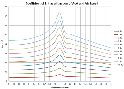
Using equation 3 for air speeds less than Mach, using equation 4 for air speeds greater than Mach, averaging the two equations at Mach, and applying some smoothing yields the below chart.
Canard Lift Force Calculation
The October 2010 test flight (described here) set the canard deflections to -2° six seconds after launch. At this time, the rocket's parameters were approximately...
| Air Speed = | 542 | ft/sec | 165 | m/sec | 0.49 | Mach |
| Altitude = | 2745 | ft | 837 | m | ||
| Air density = | 1.0614 | kg/m^3 | estimated from altitude | |||
| S = | 32 | in^2 | 0.02065 | m^2 | includes both canards and body interference | |
Plugging these numbers into the equation 1, we get an answer of 51.1 Newtons (11.5 lbf). The canard center of pressure is 2.667 inches from the rocket's center line so the rolling moment generated is 2.55 ft-lbs. I thought that a torque of 2.5 ft-lbs would have effected the rockets roll, but the flight results don't show any effect.
There are several possible reasons for this lack of effect.
- The rolling moment generated by the canards will be resisted by the rear fins. Since there are four rear fins and only two canards, and each rear fin is larger than the canard, the effectiveness of the canards may be reduced substantially. (The canards generate only 7.5% of the torque that the rear fins generate.) However, I think that this area ratio should effect the equilibrium roll rate and should not completely cancel the effect of the canards until that roll rate is achieved. The equilibrium roll rate was estimated at .38 Hz.
- The effective area of the canards included the body area between the canards. Although this appears to be valid when the YP and YN canards are in the same plane, it may not hold when they are rotated in opposite directions to cause roll.
- Canard-Tail interference. The vortex generated by the canard may be interfering with the aerodynamics of the rear fins. The vortex formed at the trailing edge of a deflected canard may pass just to the side of a fin, reducing the pressure on that side of the fin. If this is occurring, then this pressure reduction will generate tail fin lift and a tail moment in the opposite direction of the canard moment. "Missile Aerodynamics" by Jack Nielsen (pg 224) states that this is a common problem.
"These [control wake] effects are usually such that the surface behind the controls tend to produce roll in opposition to that developed by the controls themselves. For canard control the reverse roll can be large enough to produce control reversal."
Since the canards are more than 10 spans ahead of the tail fins, I had not expected this wake to be a problem, but it's clear that more analysis is needed.
Computational Fluid Dynamics Study
Mike Kolesar and Nate Siu, graduate students in San Jose State University's advanced CFD class performed a study of the Totally Stable rocket in its October 2010 flight configuration. Their results confirm that there is significant canard-tail interference and that the tail interference cancels the rotational force created by the canards.
The above report shows the pressure distributions difference between the two sides of the canard are reversed on the rear fins.
This is very evident in the study cases of greater canard deflections. When the canards are deflected to 8 degrees, the canard induced streamlines can be seen spiraling around the rocket body until they reach the rear fins. At that point the fins straighten the streamlines, canceling the effect of the canard deflection.
Image TBD
