
Attitude Stability Unit (ASU)
| Rocketry Home |
| Feretich Home |
 |
 |
Project Goal
Last year we launched our 2-stage Super-ARLISS twice. The Super-ARLISS is a big and slow rocket intended to carry payloads to 30,000 feet. We launched it at Mavericks 2008 with a very long inter-stage delay (8-seconds) and at XPRS with a short (1-second) delay. Both times it was significantly affected by the winds aloft. After the second flight, we decided that we needed to do something to dynamically compensate for crosswind. This project is to build a device that can dynamically compensate for wind and other flight perturbations and keep a rocket flying straight up.
Project Description
The project we defined is to design and build a modular compact control unit that would be aware of a rocket’s position and attitude, and make flight adjustments to keep the rocket traveling straight up. The initial version of the ASU was designed to fit in a 4" diameter rocket and use canards to control the flight profile. It is intended for Super-ARLISS class rockets that are relatively slow and only fly in the lower atmosphere. The electronics and software are expected to be reusable for thruster based control systems that would be effective on higher altitude flights.
The characteristics of the ASU are:
- Four independently controlled canards mounted at the base of a nose cone.
- The canards are controlled by geared digital servomotors. Servo PWM control signals are generated by a control computer.
- The canard deflection angles are directly sensed and input to the control computer.
- A 6-DoF MEMS sensor is used for 3-D gyroscope and accelerometer input to the computer.
- The control computer is based on the 500 MHz OMAP3 TI processor chip. It has a 64-bit super-scalar (simultaneous add/subtract, multiply, divide, and sqrt operations) floating point coprocessor. It’s basically a mathematics supercomputer in a 2 Watt chip on a 3” square board.
- The initial ASU is designed to mount in a 4” dia. Rocket. It is 12” long and resides mostly in the nosecone so that the net increase in rocket length is about 5”.
Test rocket specifics:
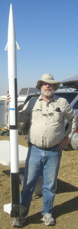
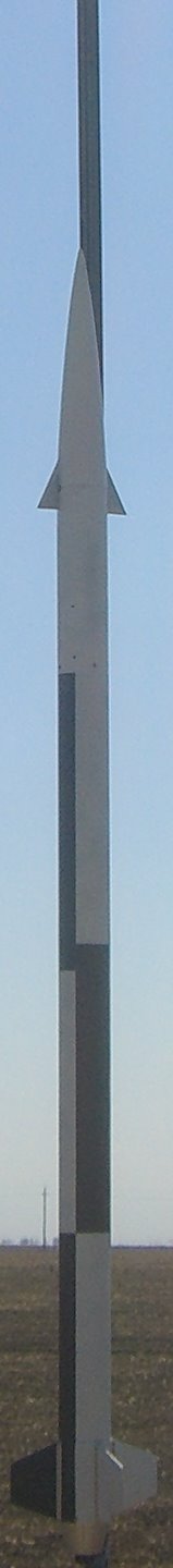
- Name: Totally Stable
- Size: 102" long (with 54 mm boat-tail adapter) and 4" dia. (actually the external fin can is ~4.25" dia.)
- Mass without motor: 6.98 kg.
- CP position: 70" from nose.
- CG position: Varies, but has a 1 static margin with the worst case motor (M1939).
Key Components
- 6-Degree of freedom (6-DoF) sensor. We have upgraded to the Analog Devices ADIS16365 sensor. This sensor contains three MEMS gyroscopes and three accelerometers that are oriented appropriately to measure acceleration and angular velocity in three dimensions. It communicates using Serial Peripheral Interface (SPI).
- Canard shaft position sensor. We decided to directly measure the angular positions of the canard shafts. We use a Avago Technologies HEDS 5500 sensor on each canard shaft. These sensors communicate via A & B quadrature output waveforms. Some models of the sensors also provide an index output, which is active when the shaft is positioned at zero degrees.
- Canard deflection servomotors. Currently, we are using a Futaba BLS153 (same dimensions as the older S9650) digital servomotor to control each canard. These motors are controlled by pulse width modulation.The input control signal period is 20 ms. Repeatedly applying a 1.5 ms pulse to this signal will make the servo seek its neutral position (0 degrees). Repeatedly applying a .9 ms pulse will make the motor seek to the 45 degree counter clockwise position. Repeatedly applying a 2.1 ms pulse will make the motor seek to the 45 degree clockwise position. Note that the canard gear wedge in the ASU will reverse the direction of rotation, multiply torque by 4.5, and reduce total movement by a factor of 4.5. Therefore, .9 ms pulses will make the canard seek a deflection of -10 degrees and 2.1 ms pulses will make the canard seek a deflection of +10 degrees.
- CPU board. The CPU board receives data from the sensors, computes the rocket's angular and linear accelerations, velocities, and positions. It then uses this information to compute a set of canard deflections that would correct the rocket's attitude. We have selected the BeagleBoard (beagleboard.org) for our CPU broad. The BeagleBoard features a 500 MHz OMAP3 processor.
- Sensor Interface Board. The sensor interface board interfaces the CPU board to the sensors and servomotors.
- The canards. The canards are small fins that can be adjusted to create a sideways force vector. The purpose of all of the above stuff is to set the canards at a deflection angle that will compensate for other side forces (internal or external) and make the rocket fly straight up.
- ASU skeleton. The skeleton is a custom aluminum frame that houses all the above components and attaches to the body of the rocket.
Mechanical Design Drawing
Structural components are made from 6061-T6 aluminum unless otherwise specified.
3-D assembly drawing
2-D assembly drawings
Delta Canard
Canard shaft
Top plate - top of the unit
Mid plate #1 - between canard compartment and servomotor compartment (74.0 grams)
Mid plate #2 - between servomotor compartment and electronics compartment (67.6 grams)
Bottom plate (tbd)
Outside canard compartment pillar and bearing support (17.2 grams)
Center bearing support block - (est. 58 grams)
Center sleeve bearing - made from Oil-Filled Bearing-Grade Bronze (SAE 841) (7.1 grams)
Canard gear wedge - made from an aluminum spur gear (35.5 grams for full uncut gear)
Electronics support bracket
Electronics compartment pillar
Servo compartment pillar (5.2 grams)The below drawings are drawings of purchased components:
Futaba BLS153 servomotor (with 48-pitch .5" pitch diameter metal gear, but also with side mounting ears removed) (30.7 grams)
Canard shaft ball bearing (outside) - note that bearings I received are slightly undersized. they slip fit into a .6247 hole.
(I guess that is what you get for $1 bearings.) (4.4 grams)
HEDS 5500 shaft position sensor (18.2 grams)
BeagleBoard (48.0 grams)
Sensor interface board height check
Electrical Design Drawings
Sensor interface board schematic
ADIS sensor adapter board schematic (mounts on the "Top Plate" next to the ADIS sensor)
Merged Sensor Interface Board Layout (yellow=top silk screen; red=top layer; green=bottom layer)
Top section = Sensor Interface Board
Left-center section = ADIS sensor adapter board
Left-bottom section = 6-pole filter and InAmp for a different project (stay tuned)
Right-bottom section = SMT soldering practice area
Software
Software: Software is expected to be the critical path of the project. We have a lot to develop and a steep learning curve. The major software modules that have been identified are:
- Embedded system cross development environment: Angstrom Linux/OpenEmbedded/Eclipse has been selected. The drivers are written in "C" and compiled via the Angstrom/OE bitbake mechanism. Application software is developed via Eclipse using the Angstrom-Linux-Arm GCC compiler. On the development bench, the root file system is mounted via NFS. This permits a quick recompile and run iteration.
- Target OS: We have installed Xenomai into the Arm OMAP3 Linux 2.6.33 kernel. Xenomai is a hard real time co-kernel that exists along side of the standard Linux kernel. Moving the drivers and time critical application code from Linux to Xenomai has significantly reduced latencies. Before we observed 150 to 200 mcrosecond jitter on the interrupt handler generation of software controlled PWM servo control signals. Now under lightly loaded conditions the jitter is impreceptable and under full load only 10 to 15 microseconds jitter is observed.
When flown, the root file system and software is run from an Initramfs (RAM disk). Telemetry data is recorded to a mounted Mini-SD-card. It is believed that not relying on the SD-card to hold the root file system will result in good system reliability even in a high vibration environment. - Real time (RT) drivers: We created two RTDM drivers. One driver controls up to four servomotors. There is PWM hardware support for three motors. The fourth motor is supported by a software constructed PWM pulse train. The other driver services the Analog Devices 6-DoF sensor and up to four HEDS shaft position sensors (interfaced via SPI bus quadrature counters). The drivers seem to be operational and stable. The ADIS driver has been enhanced to sense the sensor that is attached and supports the ADIS1635x, ADIS1636x, and ADIS164xx families of sensors.
- RT user task: This task performs Navigation and Servo-control calculations. Both algorithms have been modeled and simulated. The Navigation algorithm seems to be performing well (from the sensor input, we can determine our attitude and velocity). The Servo-control algorithm is unstable. Convergence on our attitude goal is intermittently perturbed. (It converges well, then makes large deviations.)
- Linux applications: The data logging application retrieves records from a memory segment that is shared with the real time user task. In this manner it is capable of recording the raw sensor data that is arriving every 1.22 milliseconds and the decisions being made by the real time Control algorithm. The shared segment is large enough so that it buffers Linux task latencies. The data logging task creates a new Linux file about every 40 seconds. This limits the file sizes to 1.6 MB and prevents a system crash from losing all the data from a flight. So far, the telemetry recording sub-system has been solid.
Flight Testing the Device
TBD. We basically plan an open loop flight where we attempt to move the canards through a prescribed sequence of movements and measure the they have on the rocket. Then attempt a series of flights starting with low subsonic flights and moving to 25,000 foot flights at speeds exceeding Mach 1.5. See the below Status section.
Gallery
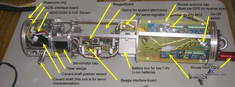
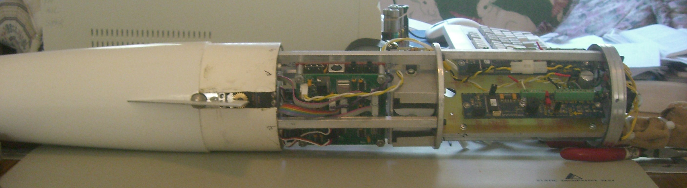
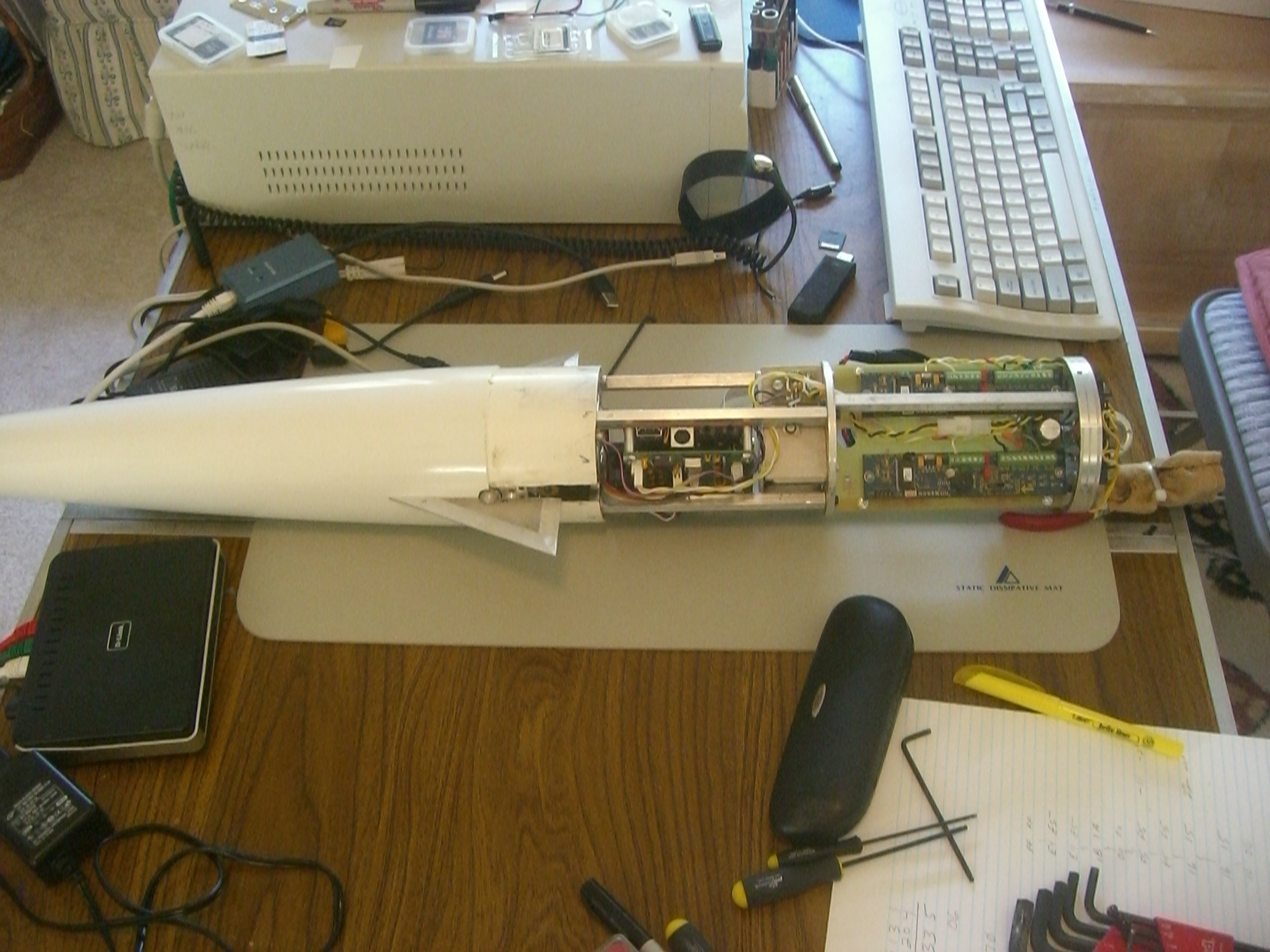
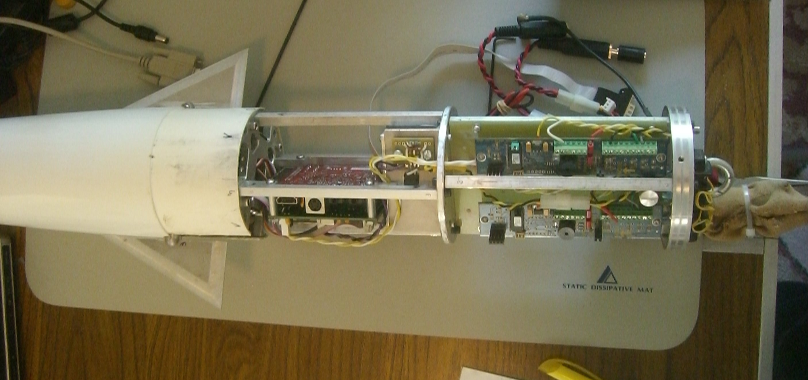
The partially completed ASU attached to the test rocket's avionics module.
 |
 |
 |
|
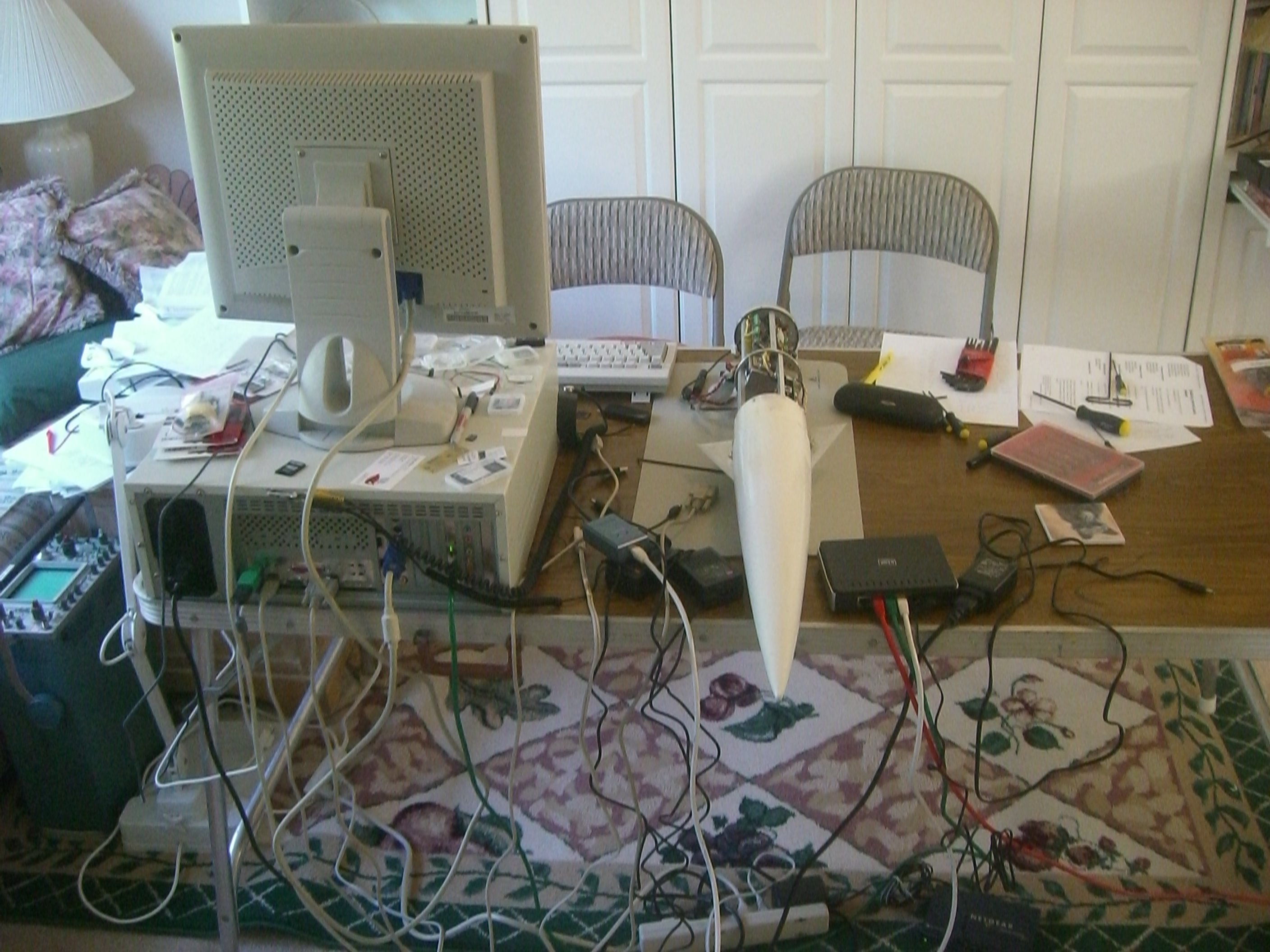
| Rocket Electronics & Software Lab | Partially Assembled ASU- Side Views | ||
 |
 |
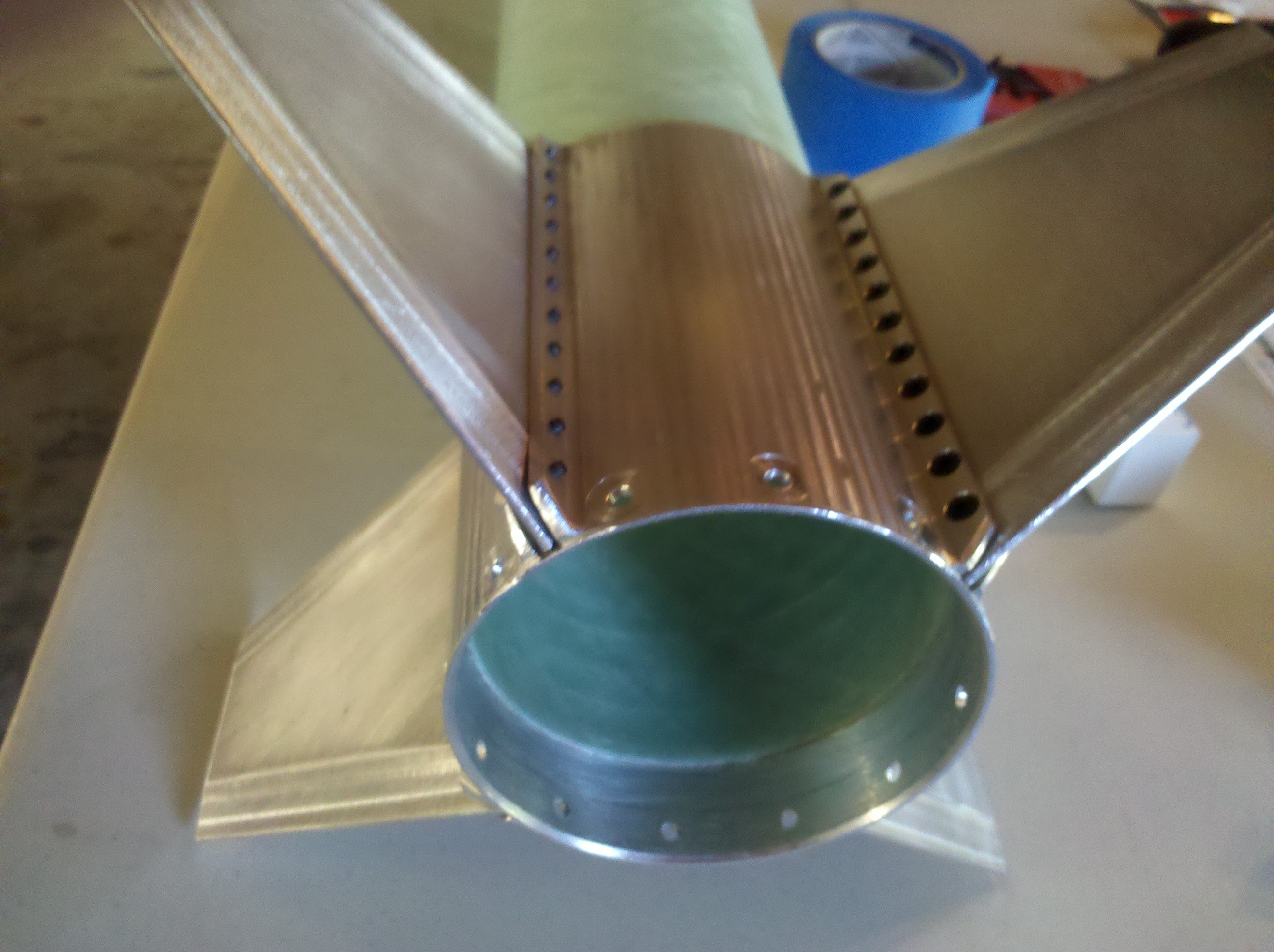 |
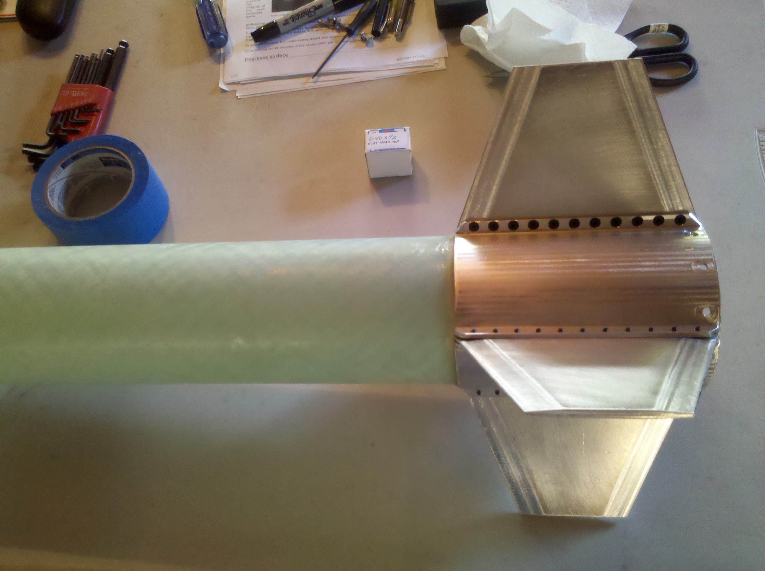
| Partially Assembled ASU - Top View | External Fin Can for the Rear Fixed Fins | |
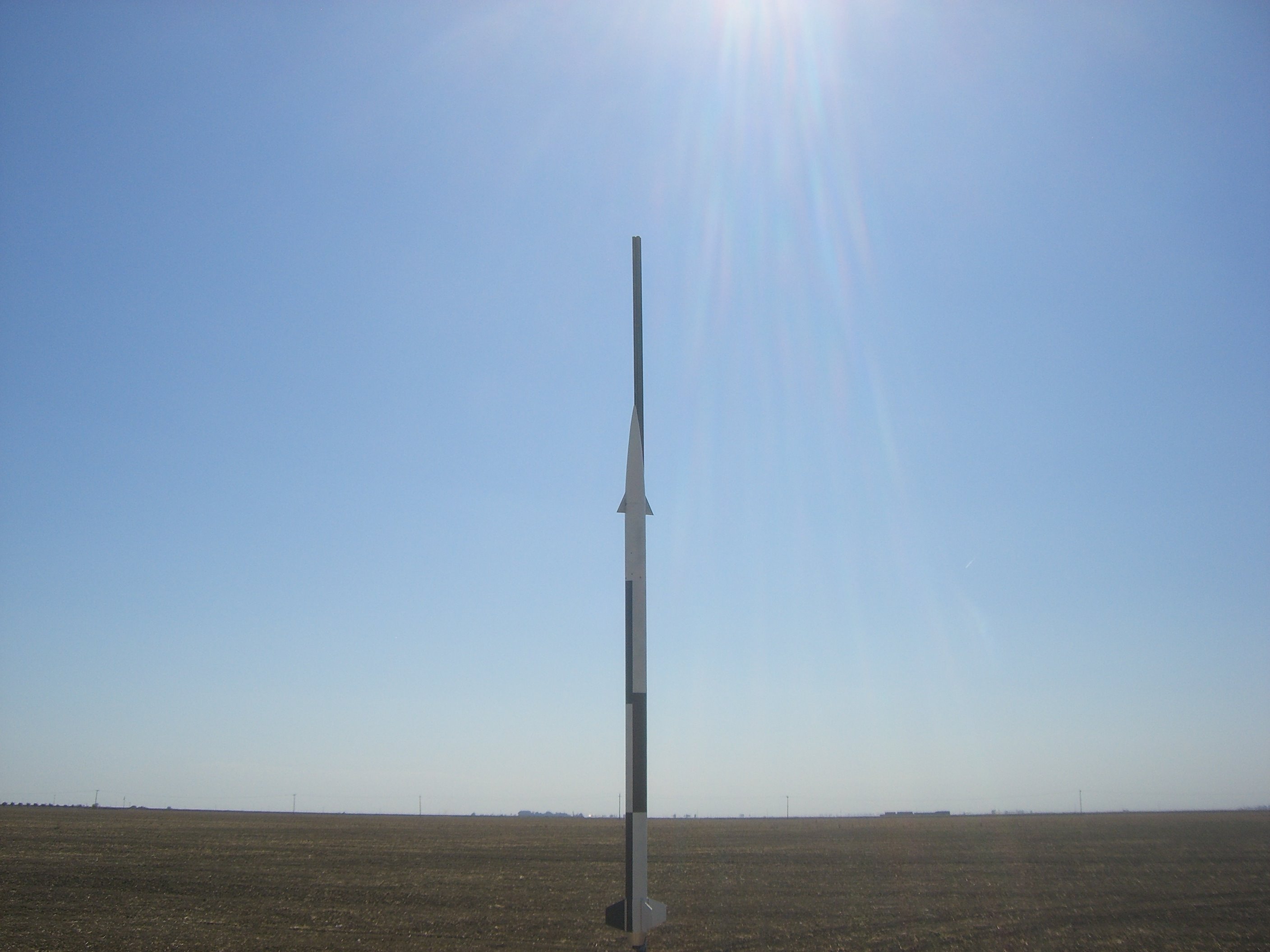
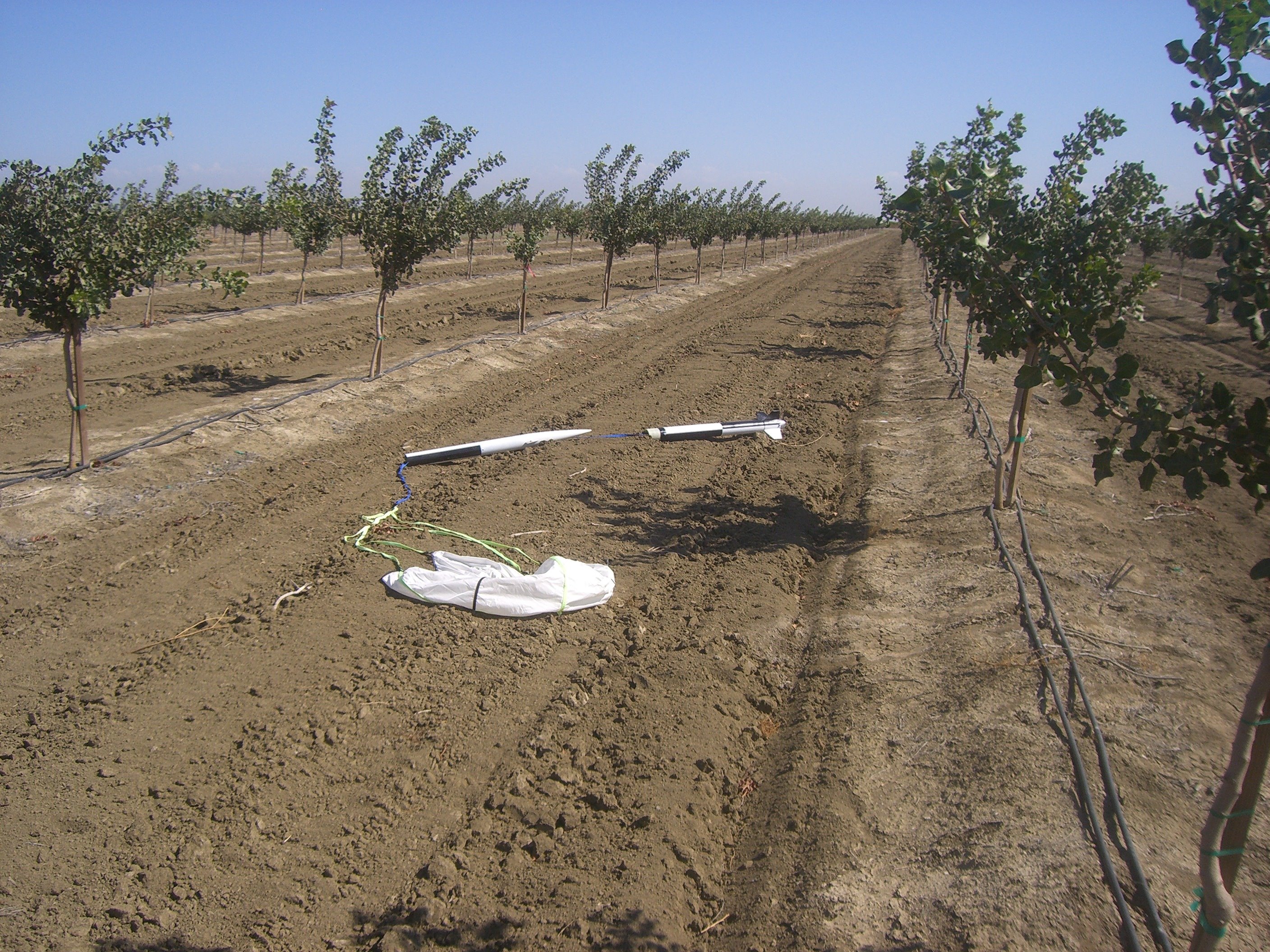
| Pictures from the October Skies Launch - 10/15/2010 | |||
 |
 |
 |
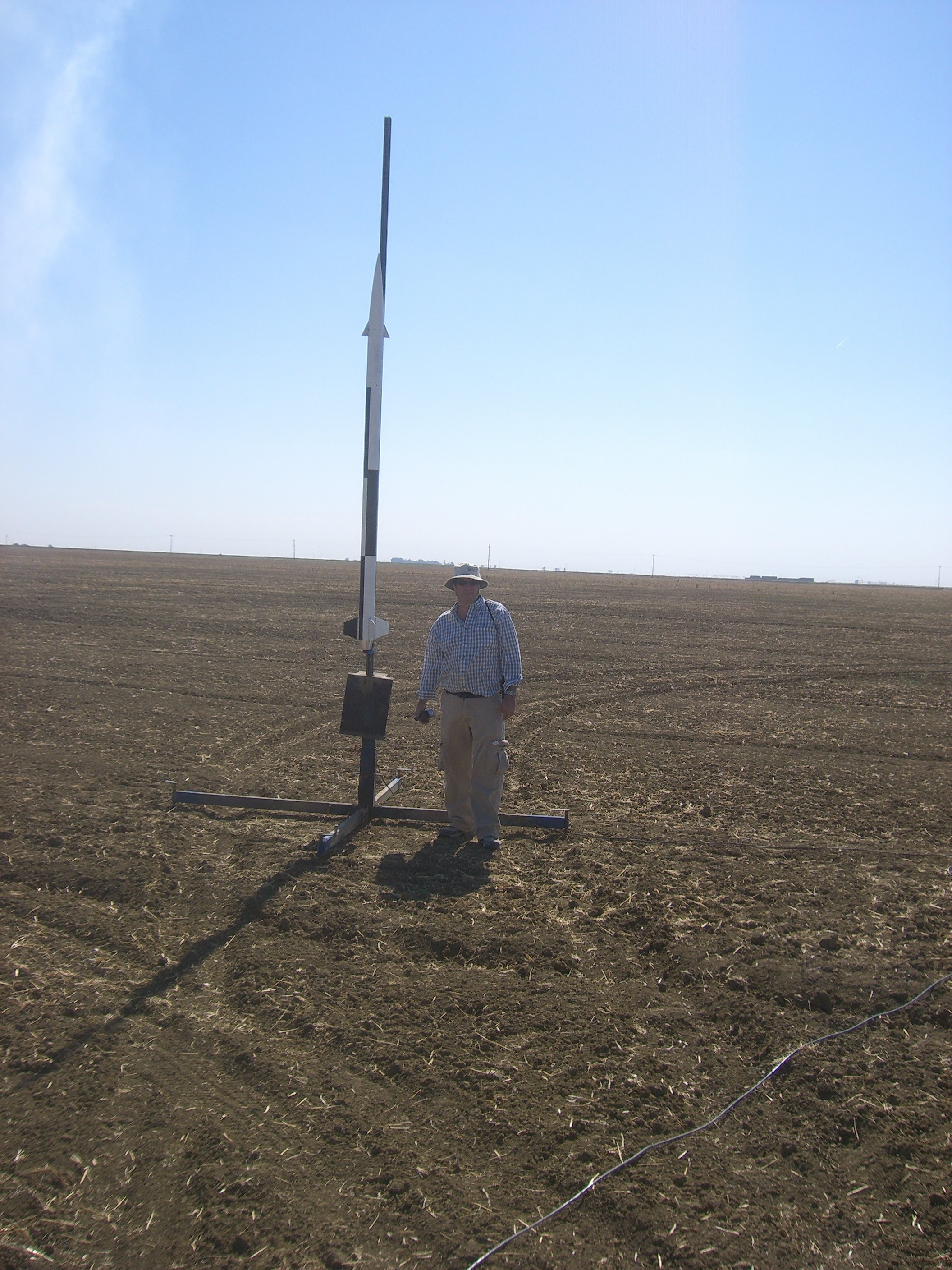 |
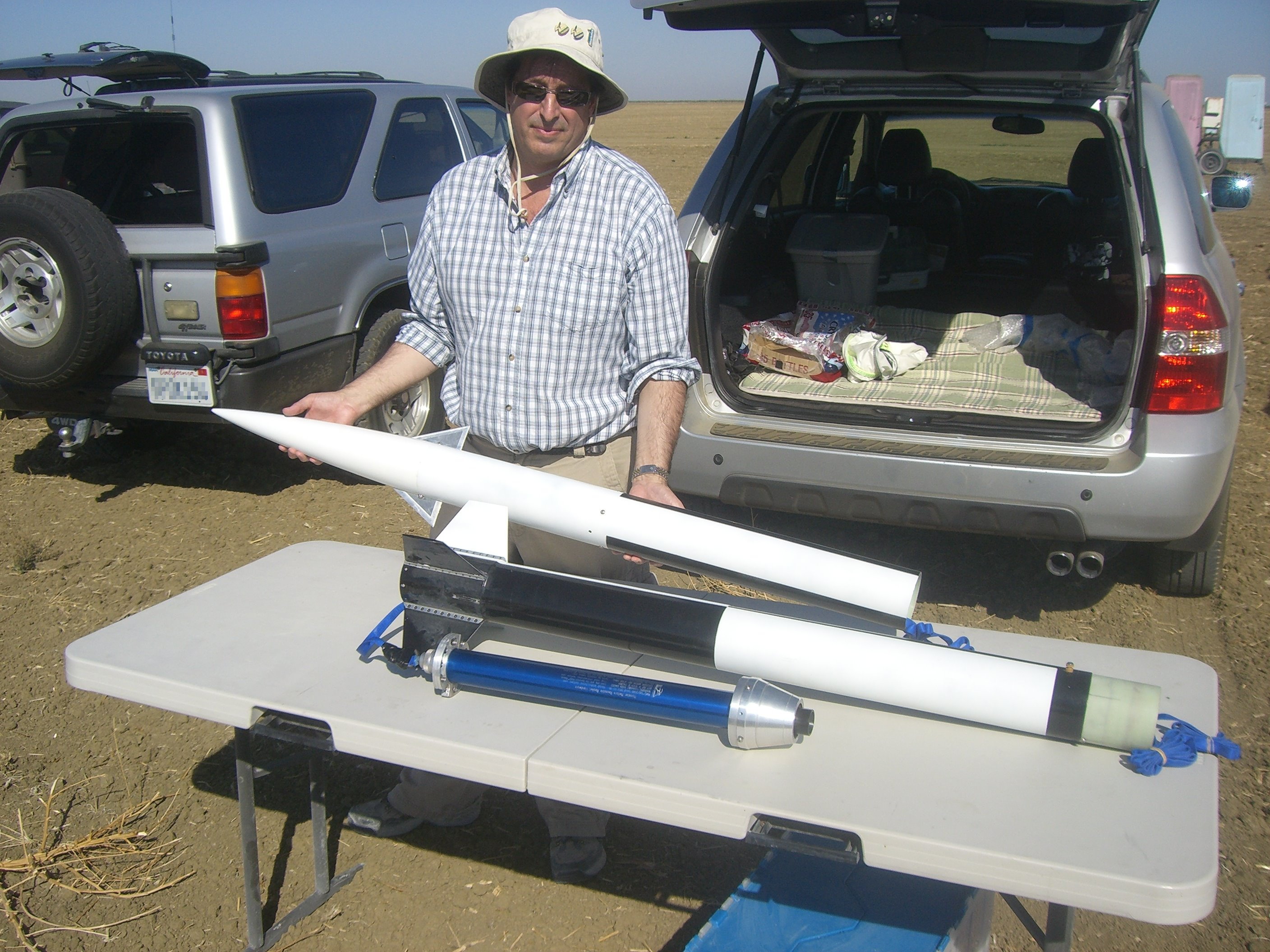
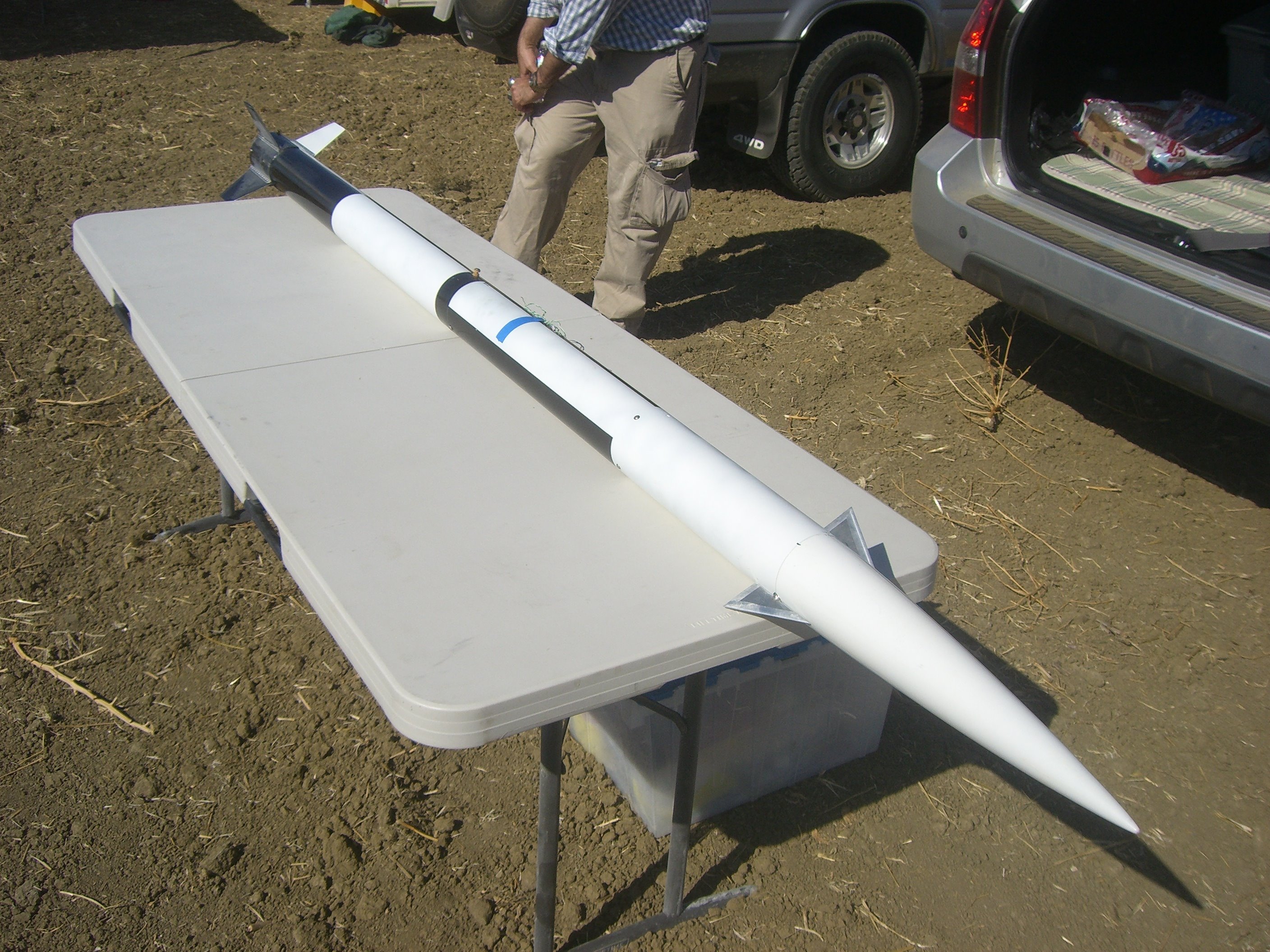
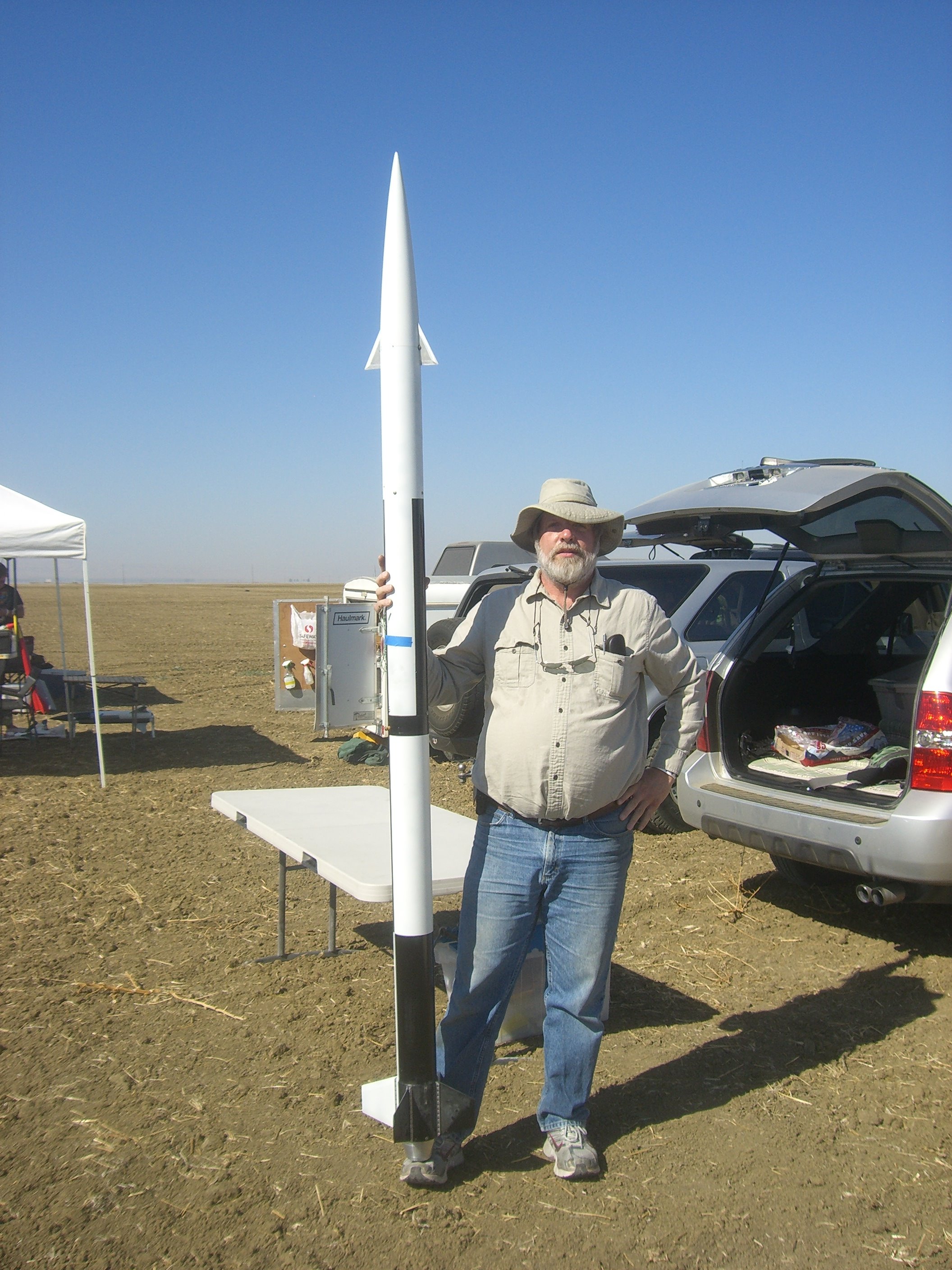
| Final Preparations | Ready to Fly | Nice eh? | A Final Check |
 |
 |
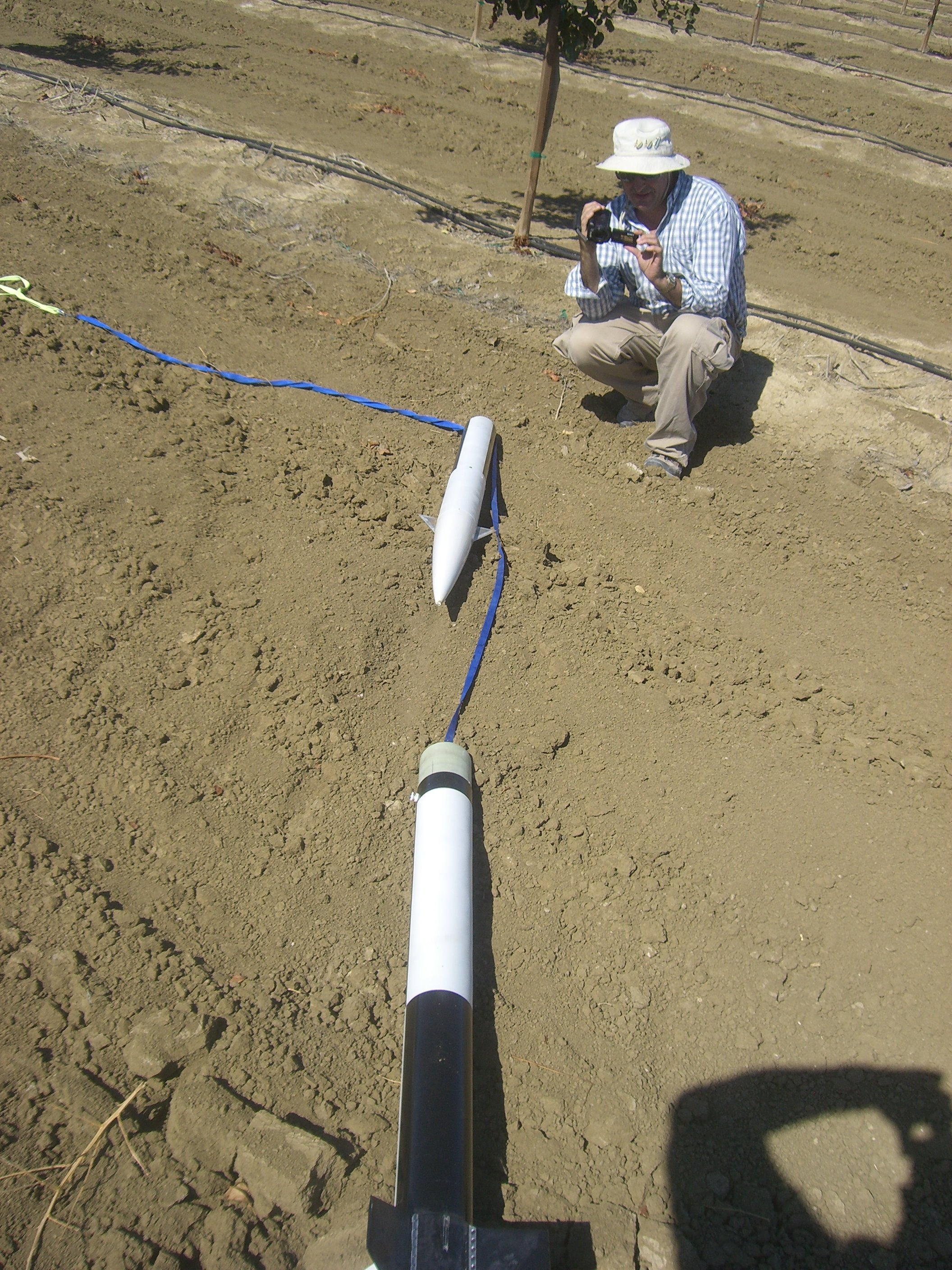 |
| 3...2...1... | Found It! | Everything's A-OK |
ASU initial bench testing:
MPEG4 video of that ASU start-up sequence.
Status
The ASU test rocket flew at October Skies on a 54mm K480W motor. The rocket flew well and we gathered good flight profile data, but the programmed roll movements did not have the effect we expected.
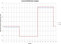
The purpose of this flight was to measure the rockets response to roll inducing step movements of the canards. Dual G-Wiz MC2 flight computers were flown to verify collected data.The flight electronics is now able to detect the launch event and command the canard servomotors to seek deflection angles at a programmable number of seconds after the event. The flight program that was executed was:
- Initial deflections = 0°
- Launch + 6 sec, -2° deflections; the negative deflections should cause a positive roll
- Launch + 13 sec, +4° deflections; the positive deflections should cause a negative roll
- Launch + 19 sec, 0° deflections
K480W flight details...
Date: 10/15/2010 Noon
Motor burnout: launch + 3.7 sec.
Apogee: launch + 20 sec.
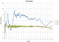
As can be seen in the below charts the ASU executed the programmed canard movements perfectly. However, there was very little, if any, effect on the rocket's roll rate. The -2° deflection that occurred at launch+6sec should have made the roll rate more positive for the period from 6 to 13 seconds. The roll becomes much more positive immediately at motor burnout and the rate slows during this period. The +4° deflection that occurred at launch+13sec should have made the roll rate more negative for the period from 13 to 19 seconds. Although the roll rate is more negative in this region, it started to go more negative before the 13 second mark. So far it appears that the canards did not cause enough torque to materially effect the roll of the rocket.
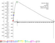 |
MC2 Flight Data |
 |
| ADIS16365 6-DoF Sensor Data | |||
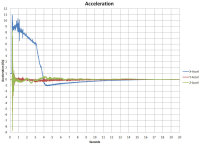 |
 |
 |
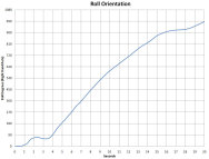 |
| Acceleration | Canard Deflection Angles | Rate Gyro Data | Roll |
Collected sensor and computed navigation flight data from launch-3sec to launch+20sec can be downloaded by clicking here (.csv). The data is in the csv comma delimited format. The field sequence is defined in the first record.
Note the Body Coordinate System (BCS, X-Axis through nose cone, Y-axis aligned with left canard as viewed from LCO table) is used for gyro rates, acceleration, canard angles, and Roll. The World Coordinate System (WCS, same as initial BCS) is used for Pitch, Heading, X-Velocity, and Altitude.
Time is in seconds from launch.
Acceleration units are Gs BCS. Values are neither adjusted for gravity nor for the sensor location being forward of the Rocket CG.
The canard deflection unit is 0.18° BCS.
Gyro rates are in °/sec BCS.
10/2/2010 update:
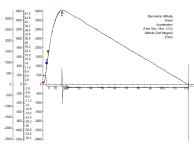
The ASU test rocket is being prepared to fly at TCC October Skies using a K480W. With this motor apogee should occur at T+20sec at about 6000 ft. An impulse roll program will be executed during the coast phase of the flight.
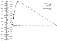
RockSim Chart for K480W
9/25/2010 update:
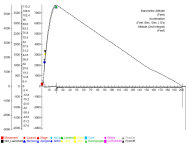
The ASU test rocket flew at XPRS on a 54mm K550W motor. Everything went as expected and we gathered a good flight profile of the K550W motor (total ISP of 1700 N-s). We tried to also profile a K480W (total ISP of 2295 N-s), but winds, low clouds, and GPS problems forced the mission cancellation.
The purpose of these flights were to gather sensor data and generate a profile of the test rocket flying various motors. Dual G-Wiz MC2 flight computers and a BoosterVision GearCam were flown to verify collected data.
K550W flight details...
Date: 9/18/2010 8:45 AM
Motor burnout: launch + 3.2 sec.
Apogee: launch + 16 sec.
Camera: The GearCam was ripped off of the rocket and destroyed. We have recovered the camera circuit board, but have not yet been able to read the video from the flash chip.
 |
MC2 Flight Data |
 |
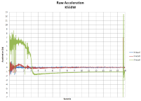
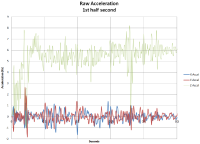
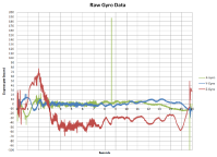
| ADIS16355 6-DoF Sensor Data | |||
 |
 |
 |
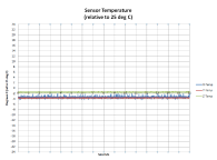 |
| Acceleration | Acceleration 0 to .5 sec | Rate Gyro Data | Temperature |
Collected sensor data for the entire flight can be downloaded by clicking here. The data is in the csv comma delimited format. The field sequence is:
<Timestamp>,<Power>,<X-Gyro>,<Y-Gyro>, <Z-Gyro>, <X-Accel>,<Y-Accel>,<Z-Accel>,<X-Temp>,<Y-Temp>,<Z-Temp>,<Status>, <XP-Deflection>,<XN-Deflection>,<YP-Deflection>,<YN-Deflection>
Note for this flight the Z-Axis is through the nosecone (sensor coordinates).. For future flights, the more standard X-axis through the nosecone (Body Cordinate System) will be used
The Timestamp is in ticks. A tick is 30.5176 usec.
A Power unit is 1.8315 mV.
A gyro unit is 0.07326°/s.
A acceleration unit is 2.522 mg.
A temperature unit is 0.1453°C relative to 25°C.
The canard deflection unit is 0.18°.
The launch occurs about half way into the file (beyond record 400,000). The pre launch data is posted to permit a study of sensor calibration and launch detection.
The Excel spreadsheet that created the charts can be downloaded here (.xlsx). It begins at the point of launch.
Testing of the real time ASU drivers was completed. Sensor data is passed from the drivers to a Xenomai user task. There is a place holder in this task for the call to the SIMD Neon Navigation Calculation Module. The task then passes the sensor and control decision data to the Linux environment, where a standard Linux process records this data to the BeagleBoard SD-card. Various shared memory mechanisms are used so that time spent copying data is minimized.
The functionality required for the first first test flight seems to be working. We are targeting the first test flight to occur during the research days of the AeroPac ARLISS/XPRS launch event (Sept. 15-18). See the ASU start-up sequence video posted above.
8/16/2010 update:
We have the Xenomai co-kernel running inside our Angstrom Linux distribution. Xenomai has greatly improved the observed latencies of the software servomotor pulse width modulation (PWM) signal generator. On the BeagleBoard, we can use 3 timers with built in PWM hardware. However, our application needs 4 PWM signal generators, one for each of the servomotors. Using the Linux version of the driver, we observed 100-200 microsecond pulse width jitter on the software generated signal on a lightly loaded system. Since the zero deflection pulse width is 1500 microseconds, this amount of jitter is unacceptable. After converting the driver to run in the Xenomai RTDM environment there was no noticeable jitter (scope was set to 200 us/div).
The Servomotor driver has been converted to RTDM and is stable.
The ASU sensor driver has been converted to RTDM, is functional, but still being tested.
Sample Test results:
The column sequence of the ADIS16355 data is...
<timestamp(32768 kHz ticks)>,<status>,<power>,<<x,y,z-gyros>>,<<x,y,z-accel>>,<<x,y,z-temp>>
Raw ADIS16355 Data tbd
Data Sanity Check Result
Excel Spreadsheet Analysis(.xlsx) (.csv) (.pdf of 1st page)
Overall, the data looks very good.
- 79,296 data packets were analyzed. (11 MB of data generated by about 1.5 minutes of testing)
- The last 111 data packets were a repeat of earlier data. We think terminating the test caused this.
- The status field always read as zeros (successful).
- The X-axis temperature values were inconsistent and often reported as not "New" even though all other data was reported as "New". So we dropped it out of the error statistics.
- 4 data packets indicated multiple "Alert" and "not New" value fields. These packets were widely separated and ignored in the below bullet remarks. (See the Data Sanity Check Result for more information.)
- 39 to 42 clock ticks occurred between data packets.
- The power supply voltage values were in the range of 4.89 to 4.92 Volts. Verified by an external voltmeter.
- The full range of gyro rate values were observed. This is probably correct.
- Linear accelerometer values -6.6Gs to +3.4Gs were observed. This is probably correct. The highest G values were recorded as we set the sensor down on a table. The +Z axis was nominally up and the Z accelerometer indicated -1G when the sensor was at rest, other axis reported near zero values. This seems correct.
- Internal temperature varied from 27.6 degC to 32.2 degC and the temperature gradually increased during the test. This seems reasonable. The Z-temperature typically tracked 2 degrees above X or Y.
- The tight ranges of status, power, and temperature; and the moderate range of accelerometer values gives us confidence that the sensor is being read and recorded correctly and reliably.
- Other instrumentation recorded that RTDM driver and an associated Xenomai RT task received the data packets and made them accessible to the non-RT Linux environment within 500 microseconds of the ADIS16355 DataReady interrupt.
Note that previous to the above testing, it was observed that about every 16th to 25th ADIS16355 DataReady interrupt occurred as a burst rather than a single interrupt. The interrupt is received on a GPIO pin and is configured to be falling edged triggered. The typical burst consisted of 11 to 16 interrupts occurring within 400 microseconds of the first interrupt of the burst. The first interrupt always occurred at about the time the DataReady interrupt was expected. These characteristics were detected by timestamping the interrupts received by the driver. We did not observe this burst phenomena on our oscilloscope, the interrupt signal looked clean. However, one in 16 to 25 may be too infrequent to be observed on our test equipment. So we are not sure if the bursts originate outside the OMAP3 chip or not. This problem was resolved by ignoring Data Ready interrupts for 500 microseconds after one is received. This ignore period is generally a good practice when using edge triggered interrupts, but it is used to filter out rare noise bursts rather bursts occurring as frequently as occurring on our test bed. Since the ADIS16355 is configured to produce a Data Ready interrupt about every 1200 microseconds, we will probably extend the "ignore" period to 900 microseconds.